


EN 7
S400
DV IN
D THEATER
REGION 1
i.LINK IN/OUT
DIGITAL OUT
OPTICAL
PCM/DOLBY DIGITAL
R
Y
L
P
B
/C
B
VIDEO
P
R
/C
R
S VIDEO
S VIDEO
AUDIO
IN
(L-1)
IN
(L-2)
REMOTE PAUSE/
AV COMPULINK
CABLE BOX
ANTENNA
ANTENNA
OUT
IN
VHF/UHF
RL
VIDEO
AUDIO
OUT
IN
COMPONENT
VIDEO OUT
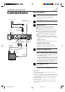
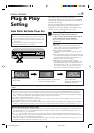
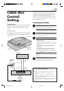
INSTALLING YOUR NEW VCR
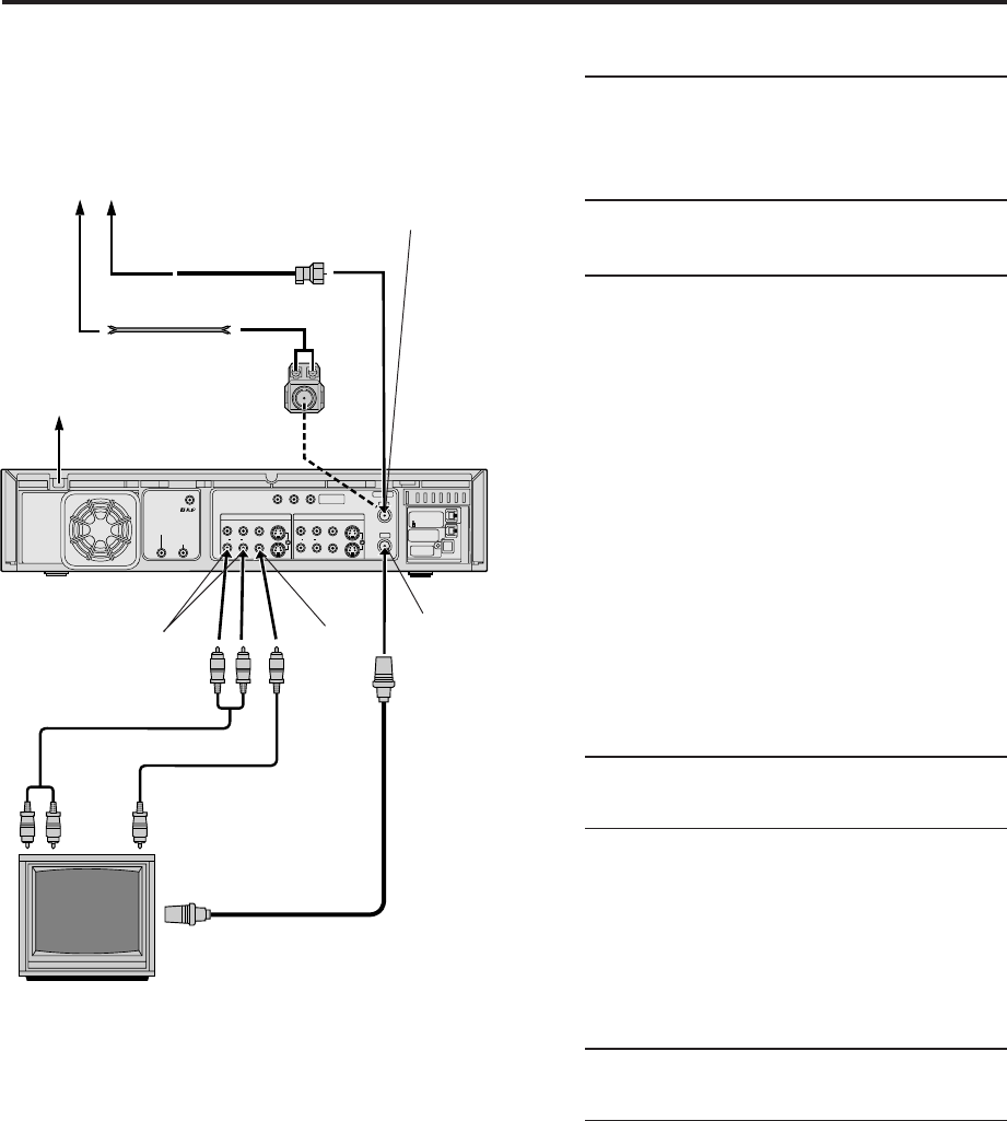
Connections
Basic Connection
1
Check contents
Make sure the package contains all of the
accessories listed in “SPECIFICATIONS”
(੬ pg. 87).
2
Situate VCR
Place the VCR on a stable, horizontal surface.
3
Connect VCR to TV
The following connections are required.
1 Disconnect the TV antenna from the TV.
2 Connect the TV antenna cable to the
ANTENNA IN terminal on the rear of the VCR.
3 Connect the supplied RF cable between the
ANTENNA OUT terminal on the rear of the
VCR and the TV’s antenna input terminal.
4 Connect an audio/video cable between the
AUDIO/VIDEO OUT connectors on the rear of
the VCR and the audio/video input connectors
on the TV.
S-VIDEO Connection
●
If you have a TV with S-VIDEO input terminals, see
“S-VIDEO Connection” on page 8.
Component Video Connection
●
If you have a TV with component video input
terminals, see “Component Video Connection” on
page 8.
4
Connect VCR to power source
Connect the AC power plug to the AC outlet.
● The clock and tuner channels will automatically
be set when the antenna is connected and when
the AC power cord is first connected to an AC
power outlet (੬ pg. 9).
(If “Auto” or channel numbers are displayed on the
front display panel before the VCR is turned on, the
clock and tuner channels are being set automatically.
Wait until the clock time is displayed on the front
display panel before turning on the VCR.)
5
Final preparation for use
Turn on the VCR.
● You can now perform basic playback
(੬ pg. 21) or basic recording (੬ pg. 26).
NOTES:
●
Your TV must have audio/video input connector for the
connection to the VCR.
●
Even if you are using audio/video cables to connect your VCR
to your TV, you must also connect it using the RF cable. This
will ensure that you can record one show while watching
another (
੬
pg. 29).
●
For full identification of the VCR’s rear panel, refer to the
Index (
੬
pg. 83).
●
If you cannot see the pictures on the TV screen when you
play back a tape, set “TV OUTPUT 1” to the appropriate
mode (
੬
pg. 56).
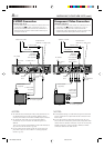
Matching
Transformer
(not supplied)
AC Power
Cord
Audio Cable
(supplied)
TV
ANTENNA IN
(Antenna or cable input)
Back of VCR
AC Outlet
Antenna or Cable
Flat Feeder
Coaxial Cable
AUDIO OUT
To Audio
Input
Connectors
RF Cable
(supplied)
To 75 Ω terminal
ANTENNA
OUT
Video Cable
(not
supplied)
To Video
Input
Connectors
VIDEO OUT
HM-DH40000U-EN01-09 1/28/3, 9:51 AM7