


Masterpage:Right-FullCol
EN 15
Filename [HM-DH5U_Eng.fm]
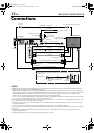
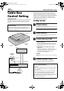
Digital Set Top Box Connection
If you are using a HD Ready TV, you can make use of this
connection to connect to the VCR.
First, check the contents and situate the VCR as instructed
in steps A and B on page 13. Then go to the following
steps.
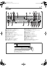
C Connect VCR to Digital Set Top
Box
A Connect an i.LINK cable between the VCR’s
[i.LINK IN/OUT] connector and Digital Set
Top Box’s i.LINK input/output connector.
B Connect an audio/S-Video cable between the
VCR’s [AUDIO/S VIDEO INPUT] connectors
and the Digital Set Top Box’s audio/S-Video
output connectors.
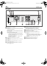
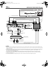
D Connect VCR to TV
A HDMI Connection
A Connect both the RF cable and the AV cables
to the TV as explained in step
C A ~ C of
‘Basic Connection’ (A page 13).
B Connect a HDMI cable between the VCR’s
[HDMI OUT] connector and the TV’s HDMI
input connector.
If your TV has only DVI input, use a HDMI to
DVI conversion cable to connect to the VCR’s
[HDMI OUT] connector. Also, connect an
audio cable between the VCR’s [AUDIO
OUTPUT] connectors and the TV’s audio
input connectors. If your TV is connected to
an AV amplifier, you can make use of the
VCR’s [OPTICAL] connector to connect to the
amplifier (A page 64).
OR
If your TV does not have a HDMI or DVI
connector, you can make a ‘Component Video
Connection’ as stated in B below, or ‘VIDEO/S-
VIDEO Connection’ as on page 13.
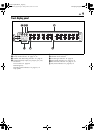
B Component Video Connection
A Connect both the RF cable and the AV cables
to the TV as explained in step
C A ~ C of
‘Basic Connection’ (A page 13).
B Connect a component video cable between
the VCR’s [COMPONENT VIDEO OUT] con-
nectors and the TV’s component video input
connectors.
C Connect an audio cable between the VCR’s
[AUDIO OUTPUT] connectors and the TV’s
audio input connectors.
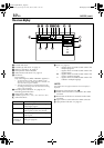
E Connect Digital Set Top Box to TV
A Connect a component video cable between
the Digital Set Top Box’s DTV (component)
output connectors and the TV’s DTV input
connectors.
B Connect an audio cable between the Digital
Set Top Box’s audio output connectors and
the TV’s audio input connectors.
F Connect VCR to power source
Connect the AC power plug to the AC outlet.
• The clock and tuner channels will automatically
be set when the antenna is connected and when
the AC power cord is first connected to an AC
power outlet (A page 16).
(If [AUTO] or channel numbers are displayed
on the front display panel before the VCR is
turned on, the clock and tuner channels are
being set automatically. Wait until the clock
time is displayed on the front display panel
before turning on the VCR.)
G Final preparation for use
Turn on the VCR.
• You can now perform basic playback (A page
28) or basic recording (A page 35).
ATTENTION:
When this VCR is connected to some HDMI devices, signals
that are normally output from the VCR in the 480i image
format may be outputted as 480p image format signals. In
such cases, signal cannot be output from the [S VIDEO
OUTPUT] connector or the [VIDEO OUTPUT] connectors.
If the [S VIDEO OUTPUT] connector or the [VIDEO
OUTPUT] connectors are used, press the [HDMI] button on
the front panel to turn off the [HDMI] LED and set “TV
OUTPUT 2” to “ALLto480i” (
A page 65).
HM-DH5U_Eng.fm Page 15 Friday, June 25, 2004 11:42 AM