3
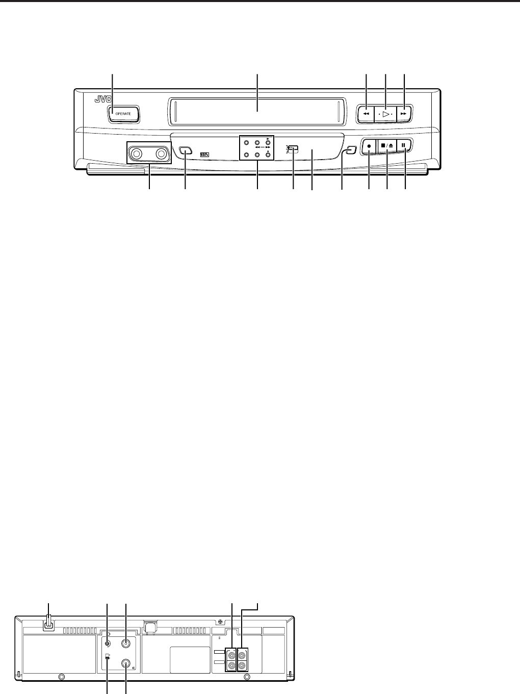
Controls and terminals
Front panel
1 OPERATE button
To turn the power on and off (standby mode).
2 Cassette loading slot
Load the video cassette here.
3 Rewind 1 button
To rewind the video tape and to start reverse shuttle search
playback mode.
4 Play # button
To start playback.
5 Fast forward ¡ button
To fast forward the video tape and to start forward shuttle
search playback mode.
6 Pause 8 button
To freeze the picture during playback. Also to engage the
recording pause mode.
7 Stop/Eject § button
To stop playback and to eject the video tape.
8 Record ¶ button
To start recording.
9 B.E.S.T. button
To set the B.E.S.T. system on.
0 Remote sensor window
For remote control operation.
! Colour System Output switch
Select to watch an NTSC tape.
@ Mode indicators
OPERATE indicator
• Lights when the power turns on.
• Blinks while a cassette is ejected.
STANDBY / Rewind 1 indicator
• Lights when the power turns off (Standby mode).
• Blinks during rewind mode.
• Blinks slowly during rewind power off mode.
Play 3 / Fast forward ¡ indicator
• Lights during playback mode.
• Blinks during fast forward mode.
• Blinks slowly during repeat playback mode.
B.E.S.T. PICTURE indicator
• Lights when the B.E.S.T. picture is on.
LP/EP indicator
• Lights the tape speed is LP(PAL) or EP(NTSC) mode.
Record ¶ indicator
• Lights during recording mode.
• Blinks during recording pause mode.
# SP/LP/EP button
To select the recording tape speed.
$ AUDIO/VIDEO IN terminals
Connect cables coming from the output terminals of another
VCR or a camcorder.
Rear panel
1 AC power cord
2 RF channel adjustment screw
3 RF. OUT terminal
4 AUDIO/VIDEO IN terminals
5 AUDIO/VIDEO OUT terminals
6 ANT. IN terminal
7 TV system switch
VIDEO CASSETTE
PLAYER
SP/LP/EP
NTSC
PLAYBACK
ON PAL TV
NTSC4.43
NTSC3.58
STANDBYOPERATE
LP/EP
B.E.S.T.
B.E.S.T.
VIDEO AUDIO
MADE IN JAPAN
HR-P128
24
1
53
76$!#098%
G
RF OUT
ANT.
IN
K
40
32
1-
VIDEO
AUDIO
IN OUT
10-
1
3
4
6
2
7
5


