5
Connections
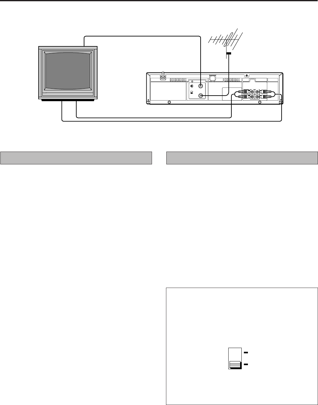
Make sure that the power to the video cassette player and TV
is off before making the following connections.
Connection A (basic)
In order to use the video cassette player it must be connected
between the antenna and the TV.
Connect your TV antenna cable to the video cassette
player’s ANT. IN terminal.
Connect one end of the provided RF antenna cable to
the video cassette player’s RF. OUT terminal and the
other end to the TV’s antenna terminal.
Connect the power cord to your household AC outlet.
1
2
3
Connection B
For connection of a TV that has VIDEO/AUDIO IN/OUT termi-
nals. This connection is necessary to record TV programmes.
Use RCA type pin connection cords (available from audio/video
stores) for connection. This connection is in addition to connec-
tion A.
Follow steps 1 and 2 of “Connection A”.
Connect the TV’s VIDEO OUT and AUDIO OUT termi-
nals to the video cassette player’s VIDEO IN and AU-
DIO IN terminals.
Connect the TV’s VIDEO IN and AUDIO IN terminals to
the VCP’s VIDEO OUT and AUDIO OUT terminals.
Connect the power cord to your household AC outlet.
TV system
The TV system switch should be set as follows.
K position: Set to this position for K system areas (East-
ern European countries).
G position: Set to this position for G system areas (West-
ern European countries for example).
1
2
3
4
Note:
• When connection B is used to connect the TV and video
cassette player, setting the TV system switch is not
necessary.
G
K
Connection B
Connection A
Note:
If you put a TV set directly on this VCP or install it too close to
a TV set, noise may occur. If this noise occurs, separate the
VCP and the TV set.
G
RF OUT
ANT.
IN
K
40
32
1-
VIDEO
AUDIO
IN OUT
10-


