


59
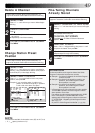
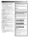
AV1 IN/OUT
AV2 IN/DECODER
AV1 OUT
COMP. Y/C
PAUSE
ANT. IN
RF OUT
S OUT
R
L
AUDIO
OUT
1
9
32 4 5
6
8
7
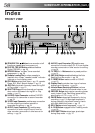
1 Mains Power Cord supplies power to recorder.
੬ pg. 6, 7
2 S OUT Connector enables S-VIDEO connection to
TV or second recorder. ੬ pg. 7, 35
3 AV1 OUT Switch selects the type of signal output via
the 21 pin AV1 IN/OUT connector. ੬ pg. 6, 28
4 AV1 IN/OUT Connector enables AV connection to
TV or second recorder; input recordable when "L-1"
selected. ੬ pg. 6, 35
5 ANT. IN Connector enables connection of aerial.
੬ pg. 6, 7
REAR VIEW
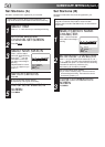
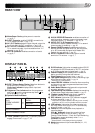
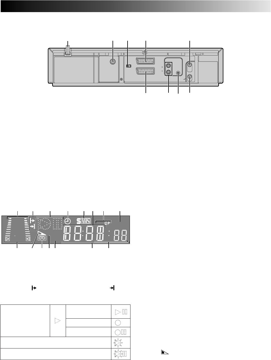
DISPLAY PANEL
1 B.E.S.T. Picture System Display lights from bottom to
top while B.E.S.T. is active. ੬ pg. 22
Audio Level Indicator displays audio input and
output levels.
2 Programme Time Indicators show the programme
start time ( ) and the programme stop time ( ) for
timer-recording. ੬ pg. 18
3 Symbolic Mode Indicators
4 "Timer" Indicator lights when ‰ has been pressed to
engage Timer mode. ੬ pg. 17, 19
5 S-VHS Indicator lights when a cassette marked S-VHS
is inserted with S-VHS mode set to "AUTO", and when
an S-VHS-recorded tape is played back.
੬ pg. 21
6 Channel Display shows preset position where the
station currently being received is stored.
Clock Display shows current time. ੬ pg. 10
7 Tape Speed Indicators display mode of recording; light
during Record or Play mode. ੬ pg. 14
* EP is only for NTSC playback.
8 Instant REVIEW Indicator blinks after timer-recording
and shows how many programmes have been timer-
recorded. ੬ pg. 26
9 Audio Mode Indicator displays audio output mode
currently selected. ੬ pg. 27
0 Tape Remaining Time Indicator displays time remaining
on tape when certain buttons are pressed. ੬ pg. 15
! "Cassette Loaded" Mark lights once a cassette is
inserted; remains lit until cassette ejected.
@ PDC Indicator lights when PDC has been engaged
for timer recording. ੬ pg. 17, 19
* VPS (Video Programme System) recording is not currently
available in the U.K. and not possible with this recorder.
# VCR Indicator lights when the video recorder is in
the video mode. At this point, the TV automatically
enters AV mode. ੬ pg. 12
$ Counter shows time elapsed since playback or
recording began.
With displayed, shows time remaining from
current tape position to end of tape (੬ pg. 15).
Counter, Preset Position*, Clock and Tape Remaining
Time Display appear alternately when – –:– –
(DISPLAY) is pressed.
* Preset Position is not displayed during playback.
% Mode shows external input mode selected (L-1, L-2,
F-1 or S-1).
REVIEW
SP
VPS/PDC
+
8
4
0
6
15dB
NORM
@
!0
$
%9
1 5 6 873 42
VCR
#
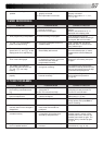
STILL:
SLOW:
RECORD:
RECORD PAUSE:
PLAY:
FF/REW VARIABLE
SEARCH:
AUDIO DUBBING:
AUDIO DUBBING PAUSE:
6 AV2 IN/DECODER Connector enables connection of
satellite receiver, decoder or second recorder; input
recordable when "L-2" selected. ੬ pg. 28, 35
7 AUDIO OUT (L/R) Connectors enable
connection of audio cassette recorder, TV or second
video recorder for dubbing. ੬ pg. 43
8 Remote PAUSE Connector enables connection to
second recorder equipped with R.A. Edit connector,
or to JVC camcorder equipped with Master Edit
Control, for easy editing. ੬ pg. 34
9 RF OUT Connector enables connection to aerial
terminal of TV receiver. ੬ pg. 6, 7