


13
D.GND
AT 1
AT 0
CS1 0
CS0 1
TMP1
SODT
SLV/MST
–
IN
OUT
IN
OUT
IN
IN/OUT
IN
D.GND
AT 0
AT 1
CS0 1
CS1 0
TMP0
SODT
D. +5 V
–
OUT
IN
OUT
IN
OUT
IN/OUT
OUT
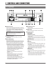
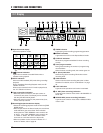
SW-501E/SW-502E
JK102/JK202
JK103/JK203
TIMER INPUT
connector
TIMER OUT
connector
Sequential switcher
SW-501E/SW-502E
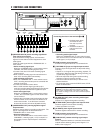
VIDEO
AUDIO
IN IN
OUT
OUT
REMOTE
MIC
IN
CAM SW
OUT
ALARM
IN
COM
COM
ALARM
REC OUT
SERIES/CLOCK
ALARM
RESET
TAPE
END OUT
WARNING
/REC
OUT
IN OUT
VIDEO
AUDIO
IN IN
OUT
OUT
REMOTE
MIC
IN
CAM SW
OUT
ALARM
IN
COM
COM
ALARM
REC OUT
SERIES/CLOCK
ALARM
RESET
TAPE
END OUT
WARNING
/REC
OUT
IN OUT
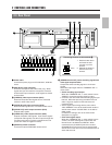
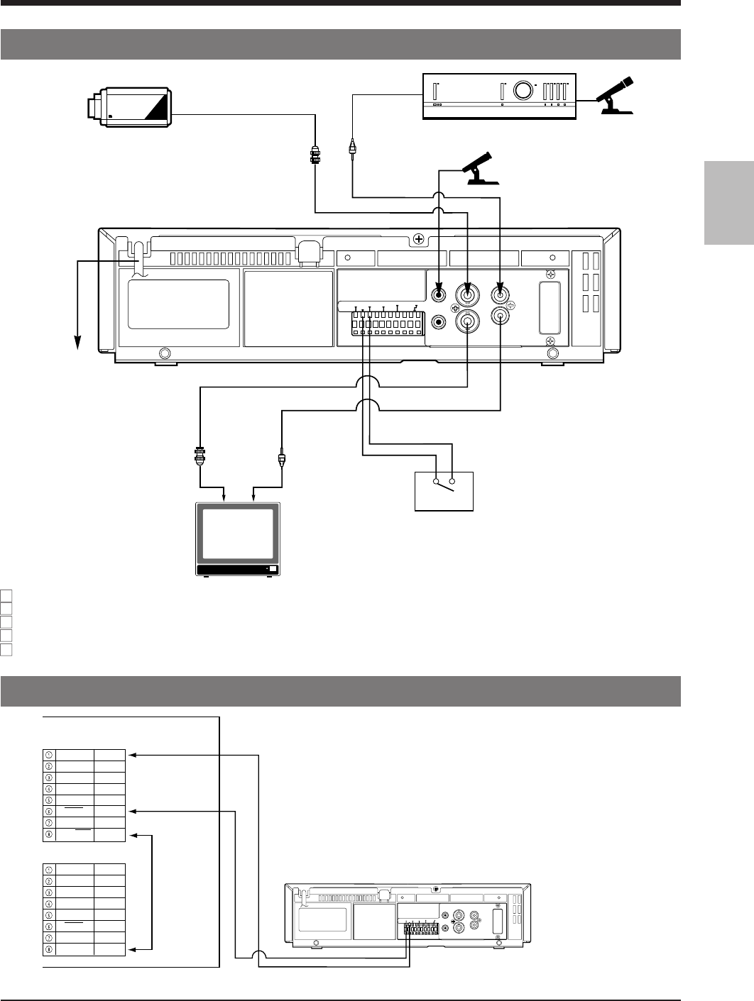
CCD
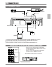
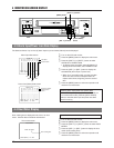
3-1 Connecting to a Camera
3 CONNECTIONS
Amplifier
Microphone
Microphone
RCA
BNC
Video camera
AC 220-240 V
BNC
RCA
Alarm sensor
Monitor TV
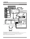
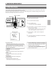
CONNECTION TO THE SW-501E/SW-502E SEQUENTIAL SWITCHER
1. Connect pin 6 on the sequential switcher's TIMER INPUT
connector to the VCR's CAMERA SW OUT terminal. Connect
pin 1 to the GND terminal.
2. Connect pin 8 on the sequential switcher's TIMER INPUT
connector to pin 8 on its TIMER OUT connector.
Note:
● Be sure to use two DIN connectors for connections.
Connect the monitor’s video/audio input connectors to the SR-9240E/EK’s video/audio output connectors.
Connect the video camera’s video output connector to the SR-9240E/EK’s video input connector.
Input audio signals to the audio input connectors via an amplifier.
When connecting an alarm sensor, connect it to the SR-9240E/EK’s alarm input terminal.
When the connection is complete, connect the power plug to an AC 220-240 V, 50/60 Hz outlet.