


Important notes for siting and installation
Place of installation
Every electronic device generates heat. The rise in temperature, however, lies within a safe range.
Slight colour changes may occur to sensitive furniture surfaces and veneers over the course of time due
to the constant effect of heat. In conjunction with treated furniture surfaces, the unit’s rubber feet can
likewise give rise to changes in colour. Where necessary, place the unit on a suitable pad.
Ventilation
The heat which is generated in this unit is dissipated quite adequately. Never install the receiver in a
cabinet, shelf or rack with inadequate ventilation. Never close off the cooling slots on the unit.
Do not place objects on top of the unit. Maintain a clearance of at least 10 cm above the unit, so that the
heat generated within the unit is conducted away without obstruction.
Humidity, exposure to sunlight, heat
Protect the unit against humidity, drips and splashing.
Do not place the unit close to radiators nor expose it to direct sunlight.
Mains voltage
Operate the receiver only from a 230V / 50 Hz mains voltage.
The unit must not be connected to the mains and switched on until after the connections have been set
up for the antenna and TV set.
Grounding
The parabolic antenna is to be grounded in accordance with regulations. The relevant local and/or
German VDE regulations are to be observed.
Remote control
Place the supplied batteries into the remote control. Ensure correct polarity of the batteries according to
the + and – markings inside the battery compartment!
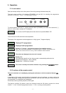
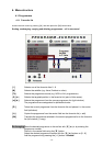
2. Connections
The following connections are located on the rear panel of the unit:
230V / 50 Hz Connect the mains cable with the mains socket.
AUDIO TV L a. R Audio output, left and right channel for connection to a stereo system.
TV Connect the TV socket to your television set with the Scart cable, which is
included in the scope of delivery.
VCR VCR Scart socket for connection of a video recorder.
SAT IF INPUT Sat IF signal input and output for LNB supply and control signals –
Connect the cable from your satellite system to this socket.
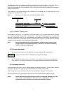
SAT IF OUTPUT IF signal output (Loop-through e.g. to an analogue receiver).
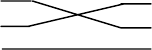
DATA INTERFACE RS 232 interface for serial data transmission for servicing.
0-modem cable (Pin 2 and 3 crossed, Pin 1, 4, 6-9 are not used).
Receiver: PC:
Pin 2 = RXD Pin 2 = RXD
Pin 3 = TXD Pin 3 = TXD
Pin 5 = GND Pin 5 = GND
- 4 -