


21
Installation and connection
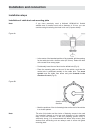
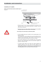
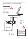
Laying cables and connecting the turntable HDP 171
• Lay the control cable (8-pole Western connector), the coaxial cable
and the power supply cable (2-pole connector) to the UFD 170.
Avoid laying the cables across sharp edges and secure the cable
against possible abrasion points.
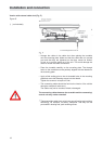
• Connect the control cable to the “POSITIONER” connecting socket
on the rear of the UFD 170. Repeat for the power supply cable,
which has to be connected to the two “POWER OUT” cables.
• Connect the coaxial cable (coming from the turntable) to the “IF IN”
F socket on the rear panel of the UFD 170.
• Place the infrared sensor close to or directly on top of the TV set
and lay the cable to the UFD 170. Connect the 6-pole Western
connector on the rear to the socket marked “IR REMOTE IN”.
Note for CAP 310: Lay the AV cinch enclosed with the CAP 310 from the HTV 115 TV
set AV cinch cable to the UFD 170 receiver.
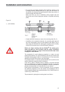
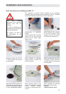
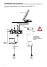
Connecting the UFD 170 to the on-board power network
Isolate the on-board network (master switch “off” or disconnect negative
pole of on-board network battery) before commencing the following
work:
• Connect the included 3-pin cable to the receiver’s “POWER IN”
plug connector.
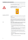
Make sure that the “inline“ integrated fuse (15 A) of the cable is
completely plugged in an intact. If the fuse responds, the source
of the fault must fi rst be eliminated. The fuse may only ever be
replaced by a fuse with the same rated value (15 A).
The fuses in the cable and in the receiver may never be bridged
– cable fi re hazard!
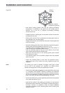
• At the connecting point for the positive and negative wires, the
voltage may not fall below 10.9 V even with a load of 12 A. Otherwise
optimum functioning can no longer be guaranteed.
• Connect the connecting cable wires marked “EARTH” (white wire)
and “+12 V” (brown wire) to the corresponding battery contacts.
Note for CAP 210: Lay the AV cinch enclosed with the CAP 210 to the Scart cable.
Here you must absolutely note the assignment of the connectors!
The cinch connector must be assigned to the UFD 170 and the
Scart connector to the TV set. Reversal is not possible – unit will not
function!