


2.2 Mounting the TracVision
Antenna
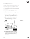
1. Make sure that you have chosen a suitable
mounting location based upon the guidelines in
“Choosing the Best Location for the TracVision
Antenna” on page 23.
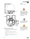
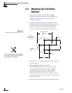
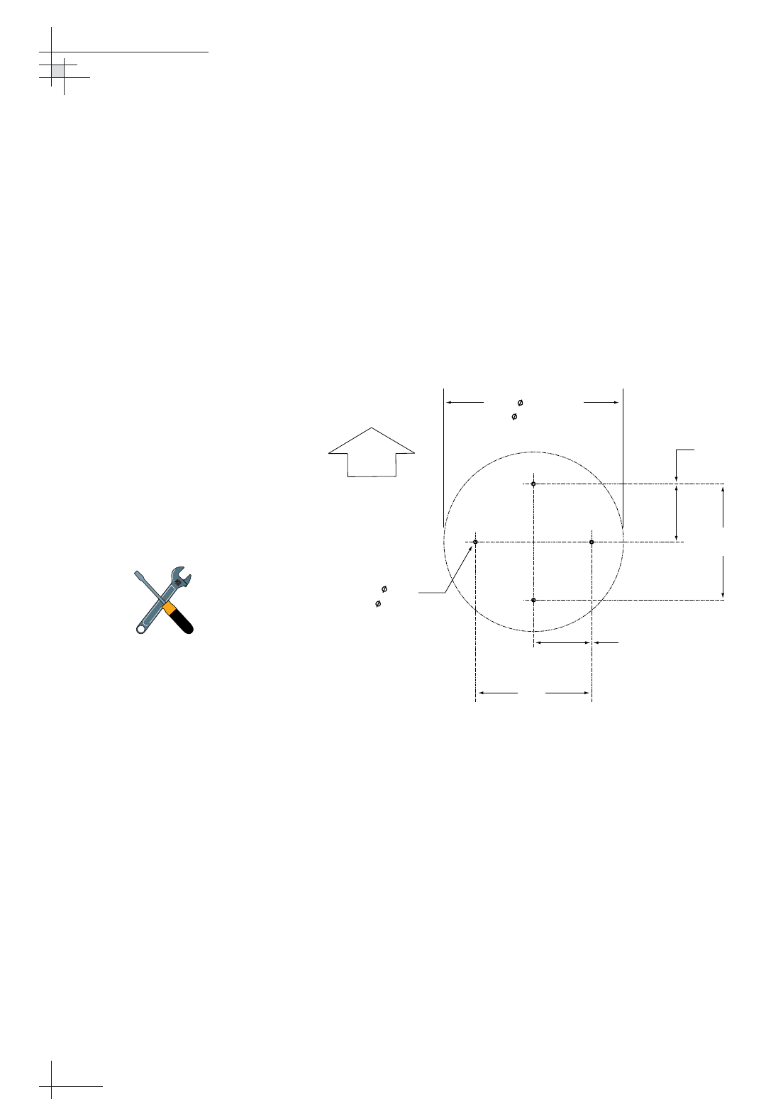
2. Using the template provided at the back of this
manual or the dimensions shown in Figure 2-3, lay
out the four mounting bolt holes. Make certain
that the “Forward” arrow is parallel with the
vessel’s centerline and pointed toward the bow.
3. Drill the four
1
⁄2
" (13 mm) bolt holes following the
layout in Step 2.
4. If mounting the antenna on a deck:
Mark a location aft of the antenna for the cable
access hole. The hole must be large enough to
accommodate the data/power cable and all
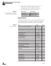
required RF cables (see Table 2-1 on page 21 to
determine the number of RF cables required). Cut out
the access hole and smooth the edges of the hole to
protect the cables.
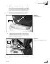
5. Remove the antenna unit from its shipping carton.
54-0198
26
TracVision G8 Owner’s Manual - Guide to Technical Information
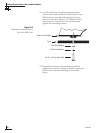
Figure 2-3
Antenna Mounting Holes Layout
FWD
4 x 0.5"
(4 x 13 mm)
12"
(305 mm)
6"
(152 mm)
12"
(305 mm)
6"
(152 mm)
Baseplate Footprint
17"
( 432 mm)
A full-size template of the baseplate
mounting holes has been provided
at the back of this manual.