


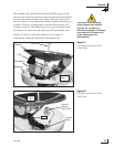
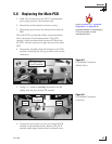
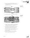
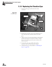
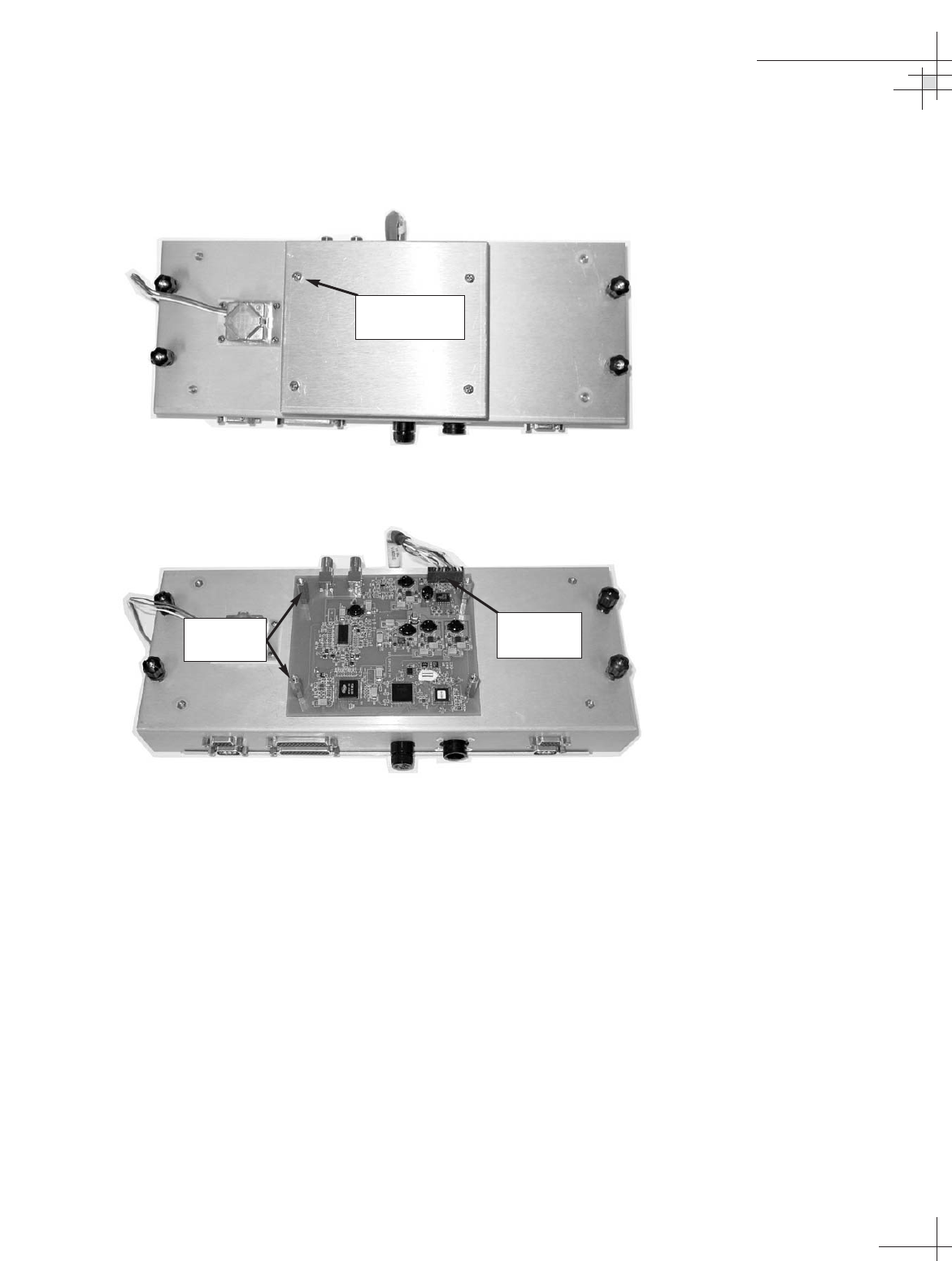
5. Remove the four #6-32 screws and flat washers
securing the RF PCB cover to the PCB module. Set
aside the RF PCB cover.
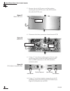
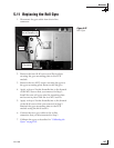
6. Disconnect the Molex connector from the RF PCB.
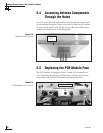
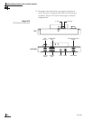
7. Using a
1
⁄4" nut driver/socket, remove the four #6-32
standoffs securing the RF PCB to the PCB module
(see Figure 5-14). Remove the old RF PCB.
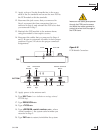
8. Apply a drop of Loctite threadlocker to the screw
ends of the six standoffs and secure the new RF
PCB to the PCB module with the standoffs.
9. Reconnect the Molex connector that you removed in
Step 6, and reinstall the PCB cover that you
removed in Step 5.
10. Reattach the PCB module to the antenna frame
using the module’s four captive screws.
Maintenance
54-0198
101
Figure 5-13
RF PCB Cover
Figure 5-14
RF PCB
#6-32 Screws
(x 4)
Molex
Connector
Standoffs
(x 4)