


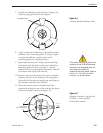
2-9
Installation
54-0157 Rev. G
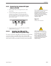
2.3 Connecting System Components
The following sections provide instructions for properly wiring
the antenna unit to the components inside the vehicle.
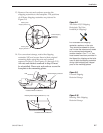
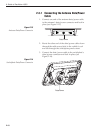
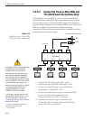
Locating the Switchplate
A switchplate has been provided to serve as the hub of the
TracVision L3/S3 wiring (with the exception of the RF cable,
which will be connected to the IRD). This switchplate includes an
ON/OFF switch and a DB9 maintenance port for easy access to
the antenna unit’s software and diagnostics. Follow the steps
below to select and prepare the switchplate mounting location.
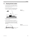
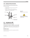
1. Select a location to mount the TracVision L3/S3
switchplate. It should be installed in a dry, flat
location within reach of the cables that will
connect to the antenna unit.
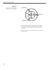
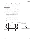
2. Once you’ve decided on a suitable location, create
a panel cutout in the mounting surface.
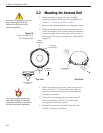
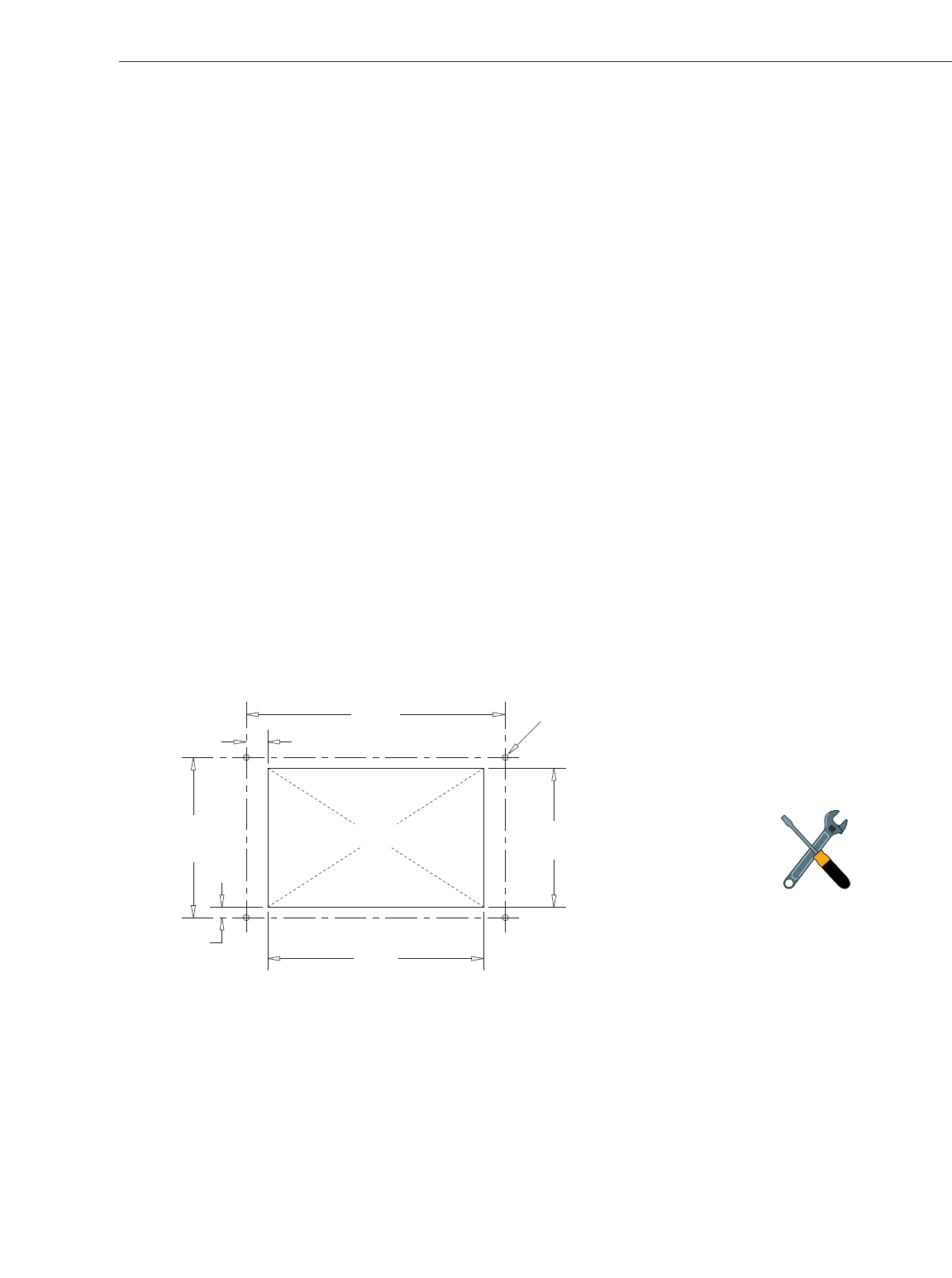
Figure 2-12 illustrates the mounting dimensions
and a template has been provided in Appendix C.
The connecting cables will be routed through this
cutout.
3.82"
(97 mm)
.32" (8 mm)
2.36"
(60 mm)
.16" (4 mm)
3.19"
(81 mm)
2.05"
(52 mm)
Panel Cutout
3
/32" (2.5 mm) dia
Figure 2-12
Switchplate Panel
Cutout Dimensions
A full-scale panel cutout template
has been provided in Appendix C.