


5-3
Maintenance
54-0157 Rev. G
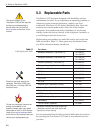
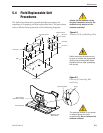
5.4 Field Replaceable Unit
Procedures
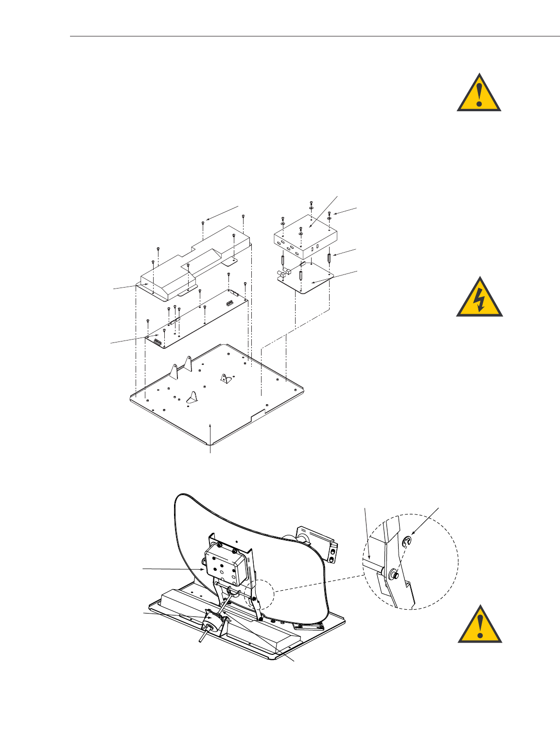
The following subsections provide detailed procedures for
repairing or swapping out field replaceable units. The procedures
refer to labeled items presented on the following diagrams.
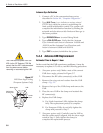
PCB
PCB Cover
Pan Head Screws
Rotating Plate
RF Board
Standoffs
RF Board Cover
RF Cover
Screws
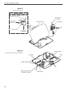
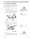
Figure 5-2
Close-up of Connecting Rod
and E-ring
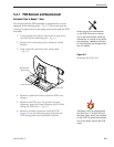
Always lift the antenna unit by
the gray baseplate, never by the
radome or any portion of the
antenna assembly!
Figure 5-1
Antenna, PCB, and Rotating Plate
Antenna Gyro
(TracVision L3 only)
E-ring
Elevation Axis
Motor Shaft
Linear Actuator
Connecting Rod
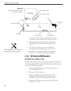
The antenna reflector is not shown
in several figures for clarity
purposes only. Do not remove the
antenna reflector!
Before servicing the antenna unit,
be sure to remove the appropriate
vehicle fuse to disconnect power.
Replace the fuse after completing
the service.