


26
EXTERNAL EQUIPMENT SETUP
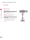
EXTERNAL EQUIPMENT SETUP
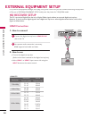
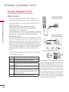
V Connect a pillow speaker to the LCD TV/Monitor.
PILLOW SPEAKER SETUP
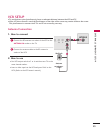
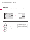
How to connect
Connect the pillow speaker (see example at right) to the
PILLOW SPEAKER interface on the rear jack panel of the TV.
PILLOW SPEAKER
Use a pillow speaker that is a UL recognized pendant control
bearing the warning:
“Risk of fire if used in oxygen enriched atmosphere.
Keep pendant control away from oxygen equipment.”
Controlling the TV with Serial Data
These TV models are capable of being controlled by a single-wire,
serial data signal. This is an LG patented technology and is being
implemented by certain brands of “smart” pillow speakers.
Pillow Speaker Interface
This connector provides an interface for patient-pendant remote
control or entertainment audio and nurse call systems. All lines are
isolated from the AC power line. (Optoisolators isolate the control
lines, and a transformer isolates the audio.) Earth ground is pro-
vided on pin 4 (Common) in the default configuration (e.g., for
Zenith/Philips pillow speakers). For negative voltage configuration
(e.g., for RCA pillow speakers), +5 volts is provided on pin 4
(Common), with pin 3 (Channel Up/Data In) referenced to
ground.
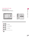
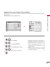
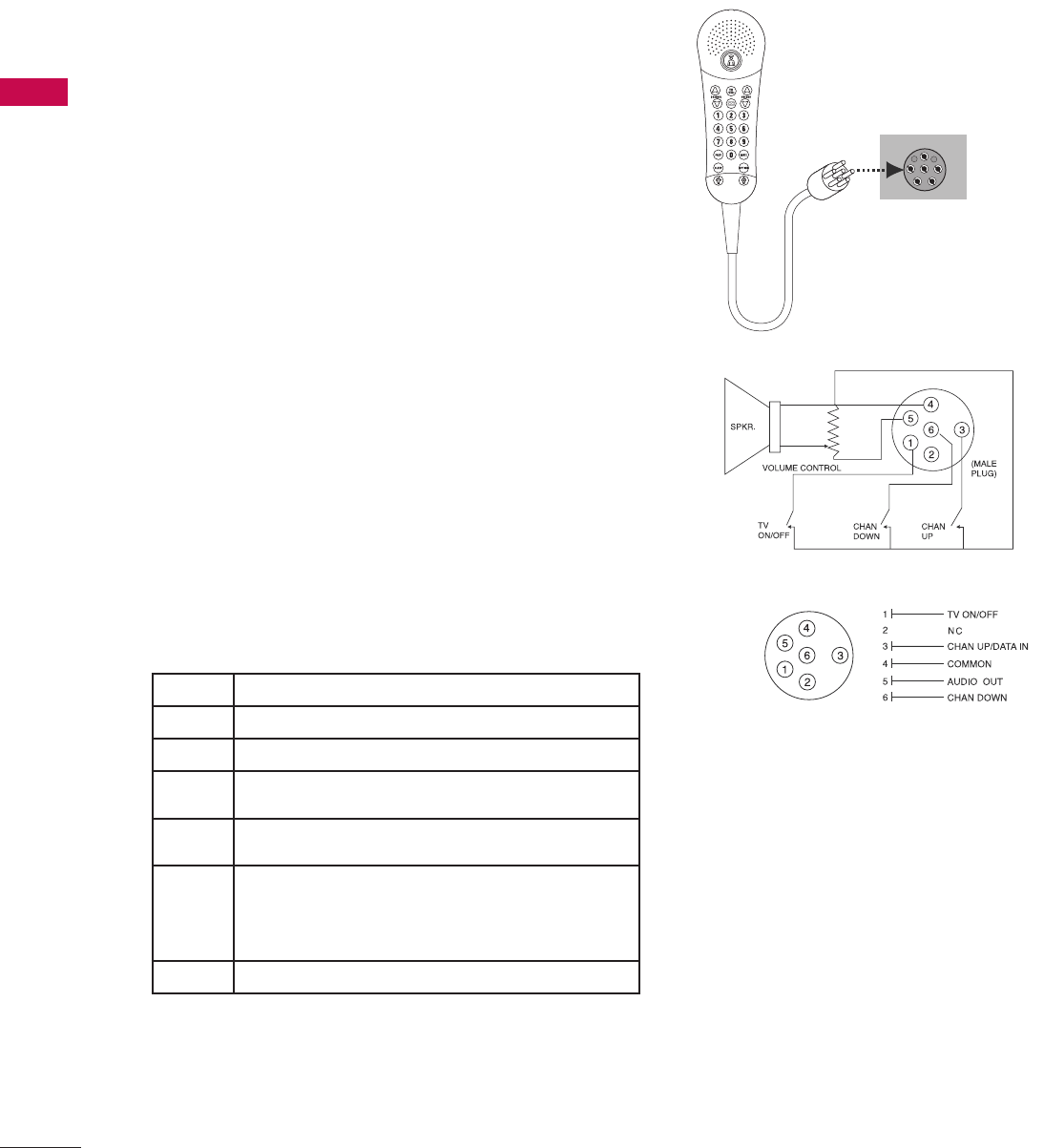
The following table describes the pillow speaker interface pinout
(see also diagram at right).
Pin No. Description
1 Analog external control for TV ON/OFF.
2 No connection
3
Analog external control for Channel Up or Serial
Data in.
4
Common connection for control, data, and audio
output.
5
Isolated Audio Output. Nominal 14 ohm source
impedance with short circuit protection. Intended
for a pillow speaker with a lowimpedance, pad-
type volume control.
6 Analog external control for Channel Down.
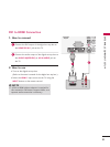
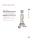
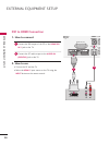
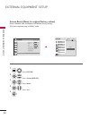
Controlling the TV with Mechanical Switches
A typical analog pillow speaker with mechanical
switches will momentarily connect pin 1, 3, or
6 to pin 4 (Common) to control Power ON/
OFF, Channel Up, or Channel Down (see sche-
matic above). These pins are at +13 volts DC
(when measured from pin 4) with the switches
open. Typical current draw is 8 mA when a
switch is closed. (This operation is identical to
previous models using the 5-wire interface,
except that only +7 volts DC was supplied and
current draw was only 2.5 mA.)
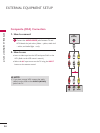
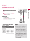
Typical Pillow Speaker
(Serial Data Control)
Typical Schematic for
Analog Pillow Speaker
Pillow Speaker Interface Pinout