


8 DLP Projection TV
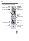
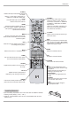
Introduction
PC/DTV
(XGA/
480p/
720p
1080i)
DVI
RGB/DVI
UPGRADE PORT
/
P
R
P
B
Y
DTV/DVD
RGB
PC/DTV
(XGA/
480p/
720p
1080i)
PC/DTV
(XGA
/480p
/720p
/1080i)
S-VIDEO
PR
PB
Y
MONO
CABLE
RGB INPUT
COMPONENT
INPUT2 INPUT1
DTV/DVD INPUT
RGB/DVI INPUT
(L)
(R)
AUDIO
(L)
(R)
AUDIO
VIDEO
(L)
(R)
AUDIO
(L)
(R)
AUDIO
MONITOR
OUTPUT
VIDEO
INPUT2
VIDEO
INPUT1
DIGITAL AUDIO
OPTICAL INPUT1
(COMPONENT2)
DIGITAL AUDIO
OPTICAL INPUT2
(DVI)
IEEE-1394
DIGITAL AUDIO
OPTICAL OUTPUT
ANTENNA
C
a
b
l
e
C
A
R
D
HDMI1
/DVI
VARIABLE
AUDIO OUT
G-LINK
HDMI2
UPGRADE
PORT
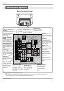
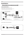
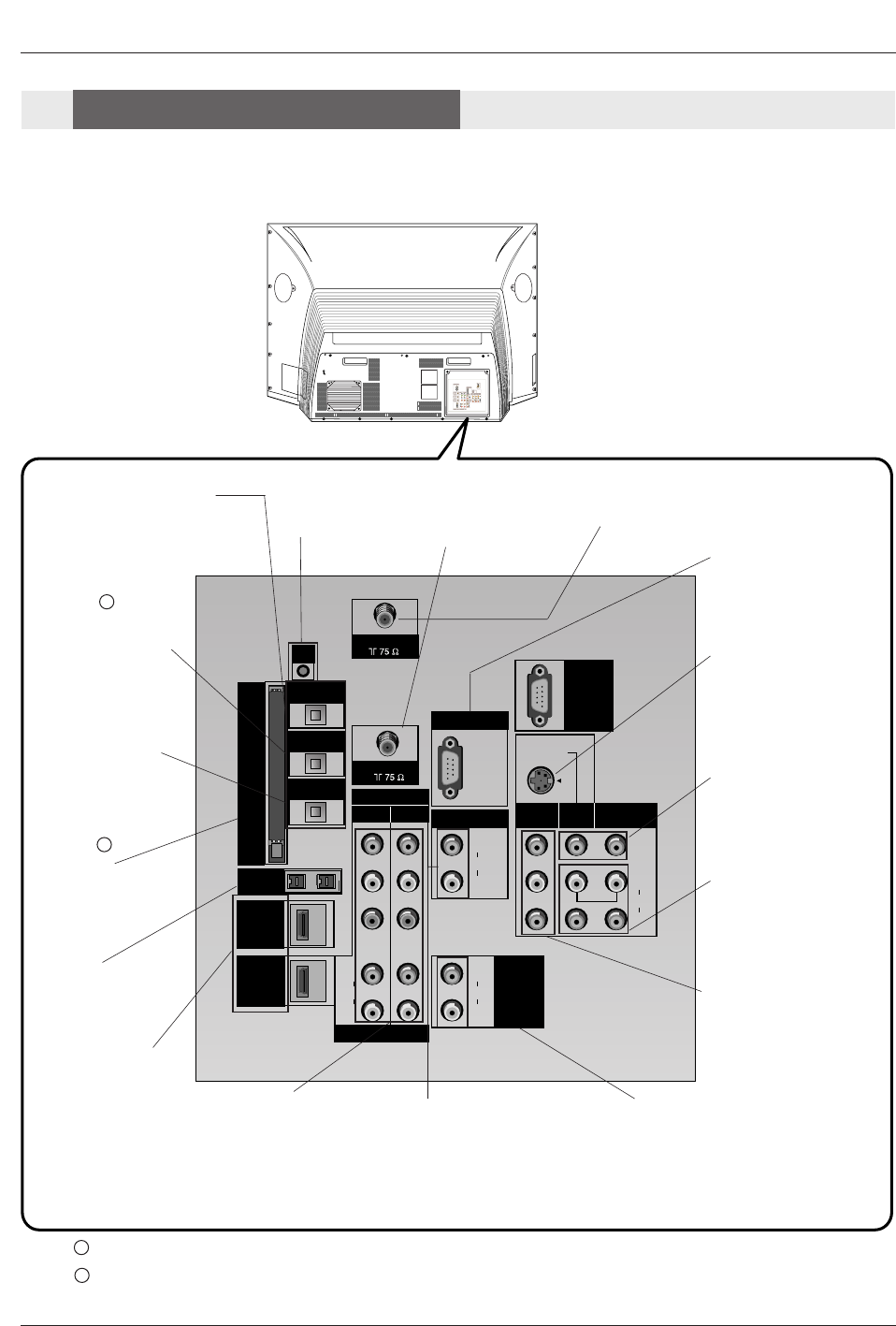
ANTENNA Inputs
Connect antenna sig-
nals to the TV directly.
DIGITAL AUDIO OPTICAL
OUTPUT
Used to connect either an exter-
nal amplifier, or add a sub-
woofer to your surround sound
system if it has a digital
audio optical input.
(Refer to )
MONITOR OUTPUT
Connect a second TV or
Monitor.
S-VIDEO In
A connection available
with some high-end
equipment that provides
even better picture qual-
ity for Video 2.
RGB/DVI INPUT
Connect the monitor
output connector from
a PC to the appropri-
ate input port.
RGB Input
Connect the TV output
connector from a PC/DTV
to the appropriate input
port.
VARIABLE AUDIO OUT
Used to connect either
an external amplifier,
or add a sub-woofer to
your surround sound
system.
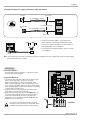
COMPONENT INPUT 1-2
Connect a component
video/audio device to
these jacks. Refer to your
DVD manual for further
information.
VIDEO 1 or 2
Connects the video sig-
nals from various types
of equipment.
Left/Right AUDIO
Used for stereo sound
from various types of
equipment.
IEEE1394
Connect DVHS or
MicroMV to IEEE1394
Connector.
CableCARD™
Used for CableCARD™
received Cable Service
Provider.
CABLE Inputs
Connect cable signals to
the TV, either directly or
through your cable box.
G-LINK
Connect a G-
LINK Cable to
this jack.
DIGITAL AUDIO OPTI-
CAL INPUT1(COMPO-
NENT2)
Connect digital audio
from the equipment
whose video is connect-
ed to COMPONENT 2.
DIGITAL AUDIO OPTI-
CAL INPUT2(DVI)
Connect digital audio
from the equipment
whose video is connect-
ed to
HDMI/DVI(VIDEO).
(Refer to )
Notes: In standby mode, these port will not work.
If the video is connected through HDMI-TO-HDMI cable, you don’t need to connect digital audio. This port
is used only when the video connected through DVI-TO-HDMI cable.
1
2
1
2
HDMI1/DVI, HDMI 2
Connect a HDMI signal
to HDMI1/DVI or
HDMI2. Or connect a
DVI(Video) signal to
HDMI1/DVI.
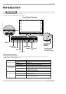
Back Connection Panel
Back Connection Panel
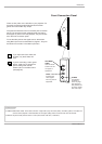
Connection Options
Connection Options