


14 DLP Projection TV
Note: The TV will let you know when the TV(analog antenna), DTV(digital antenna), CATV(analog cable) and CADTV(digital
cable) channel scans are complete.
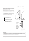
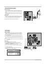
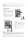
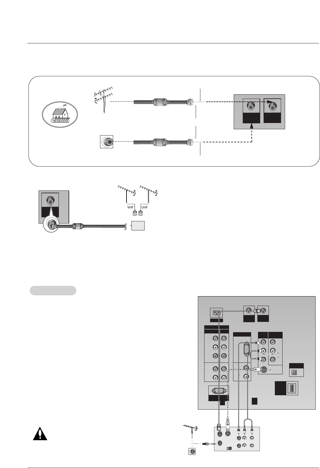
• To improve the picture quality in a poor signal area,
please purchase a signal amplifier and install properly.
• If the antenna needs to be split for two TV’s, install a “2-
Way Signal Splitter” in the connections.
• If the antenna is not installed properly, contact your deal-
er for assistance.
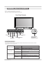
ANTENNA
IN
Signal
Amplifier
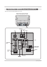
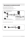
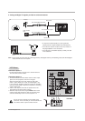
3. Analog and Digital TV signals provided on cable and antenna
Antenna
RF Coaxial Wire (75 ohm)
Bronze Wire
Turn clockwise to tighten.
Cable TV Wall
Jack
RF Coaxial Wire (75 ohm)
CABLE
IN
ANTENNA
IN
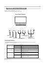
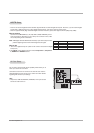
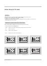
Connection Option 1
Set VCR output switch to channel 3 or 4 and then tune the
TV to the same channel number.
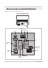
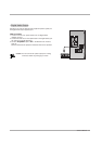
Connection Option 2
1. Connect the audio and video cables from the VCR's output
jacks to the TV input jacks, as shown in the figure.
When connecting the TV to VCR, match the jack colors
(Video = yellow, Audio Left = white, and Audio Right = red).
If you connect an S-VIDEO output from VCR to the S-VIDEO
input, the picture quality is improved; compared to connecting
only the Video input.
2. Insert a video tape into the VCR and press PLAY on the
VCR. (Refer to the VCR owner’s manual.)
3. Select the input source with using the INPUT button on the
remote control. Note that this TV finds the connected input
sources automatically for AV 1-2 and Component 1-2.
Do not connect to both AV1-2 and S-Video at the
same time. In the event that you connect both AV and
the S-Video cables, only the S-Video will work.
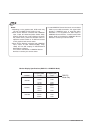
VCR Setup
VCR Setup
S-VIDEO
(R) AUDIO (L)
OUT
IN
VIDEO
34
OUTPUT
SWITCH
ANT OUT
ANT IN
RGB
(PC/DTV)
S-VIDEO
PR
PB
Y
MONO
RGB IN
COMPONENT IN
2
1
(L)
(R)
AUDIO
RGB/DVI
(L)
(R)
AUDIO
VIDEO
(L)
(R)
AV IN 1
AV OUT
DIGITAL AUDIO
OPTICAL OUT
SERVICE ONLY
VIDEO
AUDIO
HDMI
/DVI IN
CABLE
IN
AC IN
ANTENNA
IN
VCR Rear
1
2
Bronze Wire