


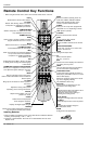
14 Plasma TV
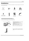
Installation
- To avoid picture noise (interference), leave an adequate distance between the VCR and TV
- Use the ISM Method (on the Option menu) feature to avoid having a fixed image remain on the screen for a long period of time.
If the 4:3 picture format is used; the fixed images on the sides of the screen may remain visible on the screen.
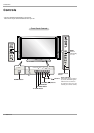
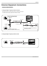
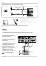
Connection Option 1
Set VCR output switch to 3 or 4 and then tune
TV to the same channel number.
Connection Option 2
1. Connect the audio and video cables from the
VCR's output jacks to the TV input jacks, as
shown in the figure.
When connecting the TV to VCR, match the
jack colors (Video = yellow, Audio Left = white,
and Audio Right = red).
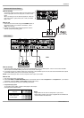
If you connect an S-VIDEO output from VCR to
the S-VIDEO input, the picture quality is
improved; compared to connecting a regular
VCR to the Video input.
2. Insert a video tape into the VCR and press
PLAY on the VCR. (Refer to the VCR owner’s
manual.)
3. Select the input source with using the
TV/VIDEO button on the remote control. (If
connected to A/V INPUT , select Video input
source)
Do not connect to both Video and
S-Video at the same time.
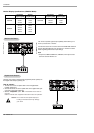
VCR Setup
VCR Setup
AC INPUTAC INPUT
S-VIDEO
OUT
IN
(R) AUDIO (L) VIDEO
34
OUTPUT
SWITCH
ANT OUT
ANT IN
DVI
COMPONENT2
DIGITAL AUDIO(OPTICAL)
VIDEO INPUT
AUDIO INPUT
CABLE
HDMI /
DVI(VIDEO)
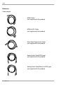
Cable
ANTENNA
VCR Rear
1
2
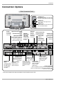
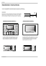
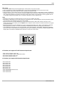
Note: The TV will let you know when the analog, cable, and digital channel scans are complete.
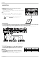
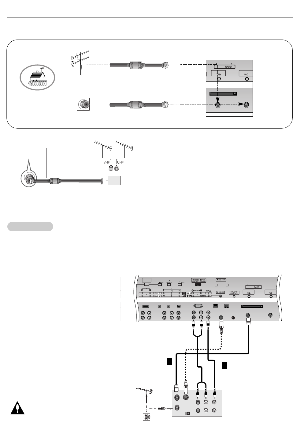
• In a poor signal area to improve picture quality, purchase
and install a signal amplifier.
• If the antenna needs to be split for two TV’s, install a “2-
Way Signal Splitter” in the connections.
• If the antenna is not installed properly, contact your deal-
er for assistance.
Signal
Amplifier
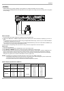
3. Analog and Digital TV signals provided on cable and antenna
Antenna
RF Coaxial Wire (75 ohm)
Analog Antenna
Bronze Wire
Turn clockwise to tighten.
Cable TV Wall
Jack
RF Coaxial Wire (75 ohm)
CABLE
Cable
ANTENNA
AC INPUT