


28
L
R
S-VIDEO
VIDEO
HDMI
S-VIDEO
R
L
Y
Pb
Pr
VIDEO
R
L
Y
Pb
Pr
VIDEO
R
L
AC IN
AC IN
HDMI
S-VIDEO
R
L
Y
Pb
Pr
VIDEO
R
L
Y
Pb
VIDEO
R
L
L
R
S
-VI
D
E
O
VI
D
E
O
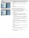
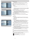
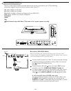
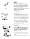
Connect Accessory Devices
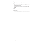
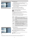
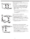
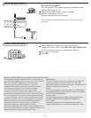
Recorder (VCR-DVD+RW)
Note: Do not place your recorder too close to the TV screen. Some
recorders may be susceptible for signals from the display. Keep recorders
a minimum distance of 20” from the screen.
There is a wide range of audio and video devices that can be connected to your TV.The following
connection diagrams show you how to connect them to the TV.
AV1 YPbPr, VIDEO and L/R Audio,
AV2 YPbPr, VIDEO and L/R Audio,
AV3 VIDEO, S-VIDEO, L/R Audio and Digital Audio out (SPDIF OUT)
SIDE VIDEO, S-VIDEO and L/R Audio, Headphone
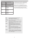
SPEAKERS
HDMI
75
Don’t insert any cable here. This area is for repair center use only.
Connect the RF Antenna or Cable TV cable (eventually through
an optional two-way signal splitter and/or Cable TV converter
box) to the RF IN socket of your
recorder.
Connect another RF cable from the output OUT of your
recorder to the TV’s CABLE/ANTENNA 75 jack.
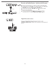
For better playback quality for stereo device only, also connect
the Video, Audio Left and Right (only for stereo devices) AV
cables to the VIDEO, AUDIO L and R input jacks of AV3.
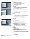
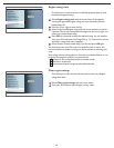
If your recorder has an S-VHS video jack:
For improved picture quality, connect an S-video cable to the
S-VIDEO input instead of connecting the recorder to the
VIDEO jack of AV3. S-Video does not provide audio, so audio
cables must still be connected to provide sound.
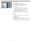
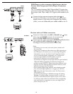
OUT
AV3:
L + R + VIDE
O
HDMI
Pb
Y
Pr
VIDEO
R
L
Y
Pb
Pr
VIDEO
R
L
S-VIDEO
R
L
3
CABL
E
IN OUT
2
ANTENNA
1
2
3