


29
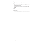
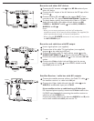
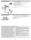
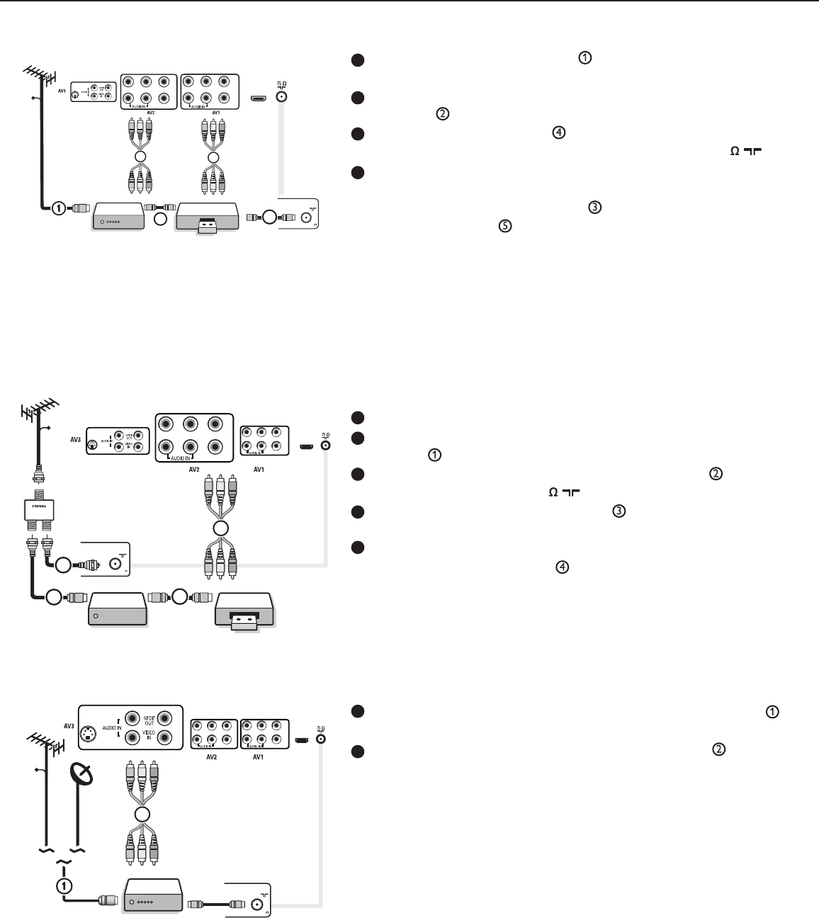
Connect the RF antenna cable of the RF IN socket of your
other AV device.
Connect the RF output of the AV device to the RF input of the
recorder .
Connect another RF cable from the output OUT of your
recorder to the TV’s input CABLE/ANTENNA 75 jack.
To obtain better quality, also connect the Video or S-Video,
Audio left and Audio right cables of both devices to AV1
(VIDEO or AUDIO L and R,) and to AV2 (VIDEO or
AUDIO L and R) .
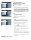
Notes:
- When you use mono equipment, only the left loudspeaker
reproduces sound. Use a mono-to-stereo adapter (not supplied) for
sound reproduction through all internal loudspeakers.
- When using the S-VIDEO connector do not connect any device to
the AV3 VIDEO input.
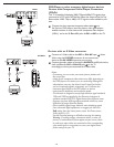
Connect the satellite antenna cable or the Cable TV cable to
the satellite receiver’s or cable box’s IN jack.
Connect the Video, Audio left and right AV cables to the
VIDEO, L and R audio input jacks of AV3.
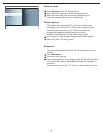
If your satellite receiver or cable box has an S-Video jack:
For improved picture quality, connect an S-Video cable to the
S-VIDEO input instead of connecting the satellite receiver or
cable box to the VIDEO jack.
Connect the audio cables to the device’s AUDIO L and R jacks
and to the L and R audio AV3 jacks on the TV.
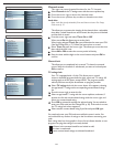
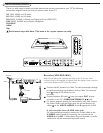
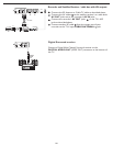
Recorder and other A/V devices
Use an signal splitter (not supplied).
Connect one of the cable TV signal splitter (not supplied)
outputs to the cable box’s IN jack.
Connect the other cable TV signal splitter output
to the
CABLE/ANTENNA 75 plug on the bottom of the TV.
Connect the cable box’s OUT jack to the recorders RF IN
socket.
Connect the Video, Audio Left and Right (only for stereo
sound) recorder AV cables to the VIDEO, audio L and R
input AV2 jacks on the TV.
Recorder and cable box with RF output
Satellite Receiver / cable box with AV outputs
HDMI 1 HDMI 2
75
CABLE OR ANTENNA
4
AV1:
L + R +
VIDEO
3
CABLE
RECORDER
OUTIN
OUTIN
2
AV2:
L + R +
VIDEO
5
Pb
HDMI
Y
Pr
VIDEO
R
L
Y
Pb
Pr
VIDEO
R
L
S-VIDEO
R
L
ANTENNA
75
CABLE OR ANTENNA
CABLE
REDROCERBTS
OUTIN
OUT
IN
SPLITTER
3
1
2
AV2:
L + R +
VIDEO
4
HDMI
Pb
YPr
VIDEO
RL
Y
PbPr
VIDEO
RL
S-VIDEO
R
L
ANTENNA
AV3:
L + R +
VIDEO
2
S
TB
I
N
CABLE
CABLE OR ANTENNA
75
HDMI
Pb
YPr
VIDEO
RL
Y
PbPr
VIDEO
RL
S-VIDEO
R
L
ANTENNA
1
2
3
4
1
2
3
4
5
1
2