


DVD
VIDEO INPUT
AUX3
VIDEO IN
L
AUDIO IN
R
DTV ANTENNA
DTV DIGITAL
AUDIO OUT
ANALOG
TV ANT/CABLE
AUX 1 AUX 2
S-VIDEO
ANALOG
AUDIO OUT
AUDIO INPUT
AUX 1 AUX 2
VIDEO OUT
VIDEO INPUT
L
R
L
R
SYSTEM AUDIO OUT
STEREO IN
6 CHANNEL
AUDIO IN
R
L
C
RS LS
SW
VGA IN
75 ohm
HIGH
SYNC
H/H + V
V
R/Pr
G/Y
B/Pb
HD COMPONENT
VIDEO IN
INTERNAL TV SPEAKERS
USED AS CENTER
CHANNEL
CENTER
CHANNEL INPUT
50 W MAX IN
– +
NO YES
SUBWOOFER
PREAMP OUT
FRONT
SPEAKERS
EXT INT
SUBWOOFER
SPEAKER OUT
– +
FRONT EXTERNAL SPEAKERS OUT
– +
– +
SURROUND EXTERNAL SPEAKERS OUT
– +
– +
All External Speakers 8 ohms Min.
R
L
R
L
AUDIO INPUT
FOR DVD,VGA,
OR HD
COMPONENTS
VIDEO S-VIDEO Pb Y Pr
SOURCE
EXIT
UP
CH
CH
DOWN
+
VOL
VOL
–
M
6
1
12:00
WXYZ
EXIT
SOURCE
UP
CH
CH
DOWN
+
VOL
VOL
–
M
3
2
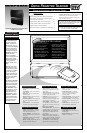
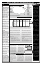
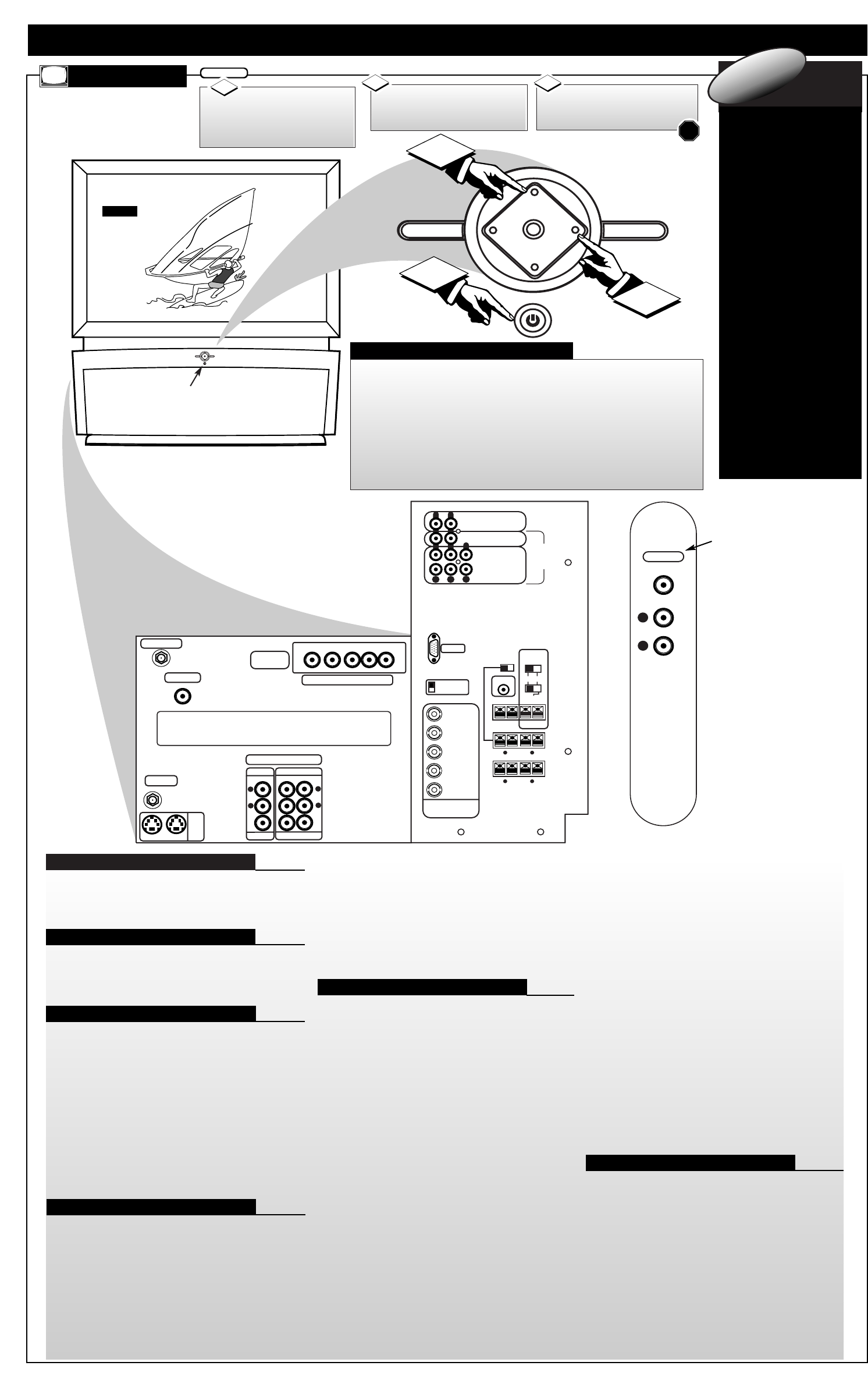
DPTV DESCRIPTION OF CONTROLS AND OPERATION
DPTV
Press the POWER
button to turn the DPTV ON.
(Green Power Light will dis-
play behind the ON button.)
Press the CHANNEL UP
or DOWN (▼) button to select
the desired TV channels.
3
BEGIN
1
STOP
2
D
igital Tele vision
(DTV) will be a v ail-
able to consumers
by o v er-the-air
broadcasts in select
city markets begin-
ning in the f all of
1998. Homeowners
can use Indoor and
Outdoor Antennas to
receive the new
transmissions, but
like previous NTSC
Analog programming
reception can be
effected by the type
and quality of the
antenna, and the ter-
rain interf erence typi-
cal to certain areas.
See page 8 for DTV s
rollout plans, dates,
and schedules.
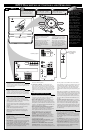
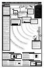
digital 1nf0rmation
• The DPTV can receive broadcasts from two antenna
sources. Connect an ATSC antenna to the DTV Antenna
jack, and a NTSC antenna, or cable TV signal, to the TV
Antenna/Cable jack.
• Multiple DVD signal connectors (Component-Y/Pb/Pr;
S-Video; or Composite) to be used for a variety of DVD
playback options. The DVD Inputs work in conjunction
with the DVD Stereo In audio jacks for sound playback.
• Three groups of NTSC Auxiliary Audio/Video Inputs can
be selected through the EXT INPUT button on the
remote, or the SOURCE button on the local keyboard.
• AUX1 - includes S-Video, CVBS Video, and accompany-
ing (Right)/(Left) channel Audio inputs.
Note: The AUX1 and AUX2 S-Video inputs work in con-
junction with the AUX1 and AUX2 audio jacks for sound
playback.
• AUX2 - identical in operation to the AUX1 S-Video,
CVBS Video, (Right)/(Left) Audio Inputs.
• AUX3 - located on the right-side of the front of the
DPTV. Jacks include CVBS Video and (Right)/(Left)
Audio inputs.
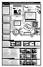
• Two sets of A/V jacks direct external source signals to
the DPTV monitor:
• VGA IN - to connect a standard VGA (Video Graphics
Array) source for display.
• HD VIDEO IN - to input digital video from an external
source such as a computer. Input jacks include BNC con-
nectors for R/Pr, G/Y, B/Pb, and H/H+ V signals.
• SYNC Switch - related to the HD Video inputs to allow
for synchronization switching between 75Ohm and High,
depending on the level of the digital source used.
• STEREO IN - jacks for (Right)/(Left) 2-channel stereo
sound to the DPTV speakers.
• 6-CHANNEL AUDIO IN - to connect Right, Left,
Center, Right Surround (RS), Left Surround (LS), and
Subwoofer (SW) audio channels from an external Dolby
Digital device. The playback of 6-channel audio is also
dependent upon the configuration and adjustment of other
jackpanel (and ATSC Speaker Menu) switches and con-
trols.
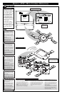
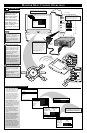
• The DPTV is capable of a variety of audio speaker con-
figurations and connections for sending six channel audio
to internal and external speakers, as well as receiving
external supplied source material for playback.
• FRONT SPEAKERS Switch - to set the output of the
DPTV’s front (R)/(L)channel audio. INT(ernal) sends
(Right)/(Left) audio through the DPTV’s built-in (R)/(L)
front speaker system. EXT(ernal) routes the (R)/(L) chan-
nel audio to the FRONT EXTERNAL SPEAKERS OUT
terminals on the rear of the DPTV.
• FRONT EXTERNAL SPEAKERS OUT Terminals -
for the playback of the DPTV's front (Right/Left)
channel audio to external speakers (if connected). Note:
These speaker terminals are only active when the
FRONT SPEAKERS switch is set to EXT(ernal).
• SURROUND EXTERNAL SPEAKERS OUT
Terminals - to send the Surround Right (SR) and
Surround Left (SL) channel audio to external speakers.
• SUBWOOFER PREAMP OUT Jack - to send the
Subwoofer audio channel (at line level) to an external
powered Subwoofer speaker.
• SUBWOOFER SPEAKER OUT Terminals - to send
an amplified Subwoofer channel audio to an external
non-powered Subwoofer speaker.
• INTERNAL TV SPEAKERS USED AS CENTER
CHANNEL Switch -
used (in tandem with the Center
Channel Input switch - see next control description) to set
the DPTV’s built-in speaker system. Place the switch to
the YES position to use the DPTV for Center Channel
audio playback (as connected and supplied from an exter-
nal Dolby Digital capable Amplifier source.) Place the
switch to the NO position to retain full DPTV internal
speaker system audio (with active Surround External
Speaker Out and Subwoofer Speaker Out terminal opera-
tion.)
Note: When the INTERNAL TV SPEAKERS and CEN-
TER CHANNEL INPUT switches are placed in the YES
position no audio will be heard through the DPTV speak-
er system (unless a Dolby Digital capable Amplifier’s
Center Channel Output terminal is connected and active
through the DPTV’S CENTER CHANNEL INPUT ter-
minals.)
• CENTER CHANNEL INPUT Switch - to control the
playback of the DPTV’s built-in speaker system for either
Center Channel audio (place switch to YES position
when connected to an external Dolby Digital capable
Amplifier’s Center Channel Output terminal); or for full
speaker DPTV system audio (place switch to NO in tan-
dem with the Internal TV Speakers switch, see informa-
tion listed above.)
• Three sets of audio output connectors and one video out-
put connector are on the rear of the DPTV.
• SYSTEM AUDIO OUT - jacks send the DPTV system
audio (ATSC, NTSC, and Monitor) to an external ampli-
fier. The DPTV outputs a 2-channel (Left/Right) stereo
audio signal.
• TV VIDEO OUT - CVBS video connector, matched
with a set of (Right/Left) Audio Outputs, used to send
NTSC video to an external source (such as a VCR, etc.)
• DTV DIGITALAUDIO OUT - RCA connector which
routes the audio from the ATSC module to an external
amplifier/decoder that accepts a SPDIF (Sony-Philips
Digital Interface Format) input source.
Antenna/Cable Inputs (ATSC/NTSC)
A/V Inputs Monitor
Audio/Video Inputs (NTSC)
DVD Video Inputs
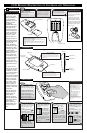
• Source - Press to cycle through
the DPTV available inputs (ATSC,
NTSC tuners and all external
inputs.)
• Menu (M) - Press to display the on-
screen control system for the
selected system. (See the ATSC,
NTSC, & Monitor sections for
details on the use and navigation
of the menus.)
• CH Up/Down - With a select Menu
system displayed, press to move
through the list of control features.
• VOL Up/Down - With a select
Menu system control displayed,
press to adjust the on-screen feature.
• Exit - Press to display a Status
screen for the selected Menu sys-
tem, or clear the screen following
Menu feature adjustments.
Rear DPTV Jackpanel
Infrared Remote Sensor Window
Side Cabinet Jackpanel
(located on Right/Front
side of DPTV)
Press the VOLUME (+)
UP or VOLUME (-) DOWN
button to adjust the sound level.
2
Audio Speaker Switches/Connectors
Audio/Video Outputs
DPTV LOCAL KEYBOARD FUNCTIONS