


General Description
The MAX5811 is a single, 10-bit voltage-output digital-to-
analog converter (DAC) with an I
2
C™-compatible 2-wire
interface that operates at clock rates up to 400kHz. The
device operates from a single 2.7V to 5.5V supply and
draws only 100µA at V
DD
= 3.6V. A low-power power-
down mode decreases current consumption to less than
1µA. The MAX5811 features three software-selectable
power-down output impedances: 100kΩ, 1kΩ, and high
impedance. Other features include an internal precision
Rail-to-Rail
®
output buffer and a power-on reset (POR)
circuit that powers up the DAC in the 100kΩ power-down
mode.
The MAX5811 features a double-buffered I
2
C-compatible
serial interface that allows multiple devices to share a sin-
gle bus. All logic inputs are CMOS-logic compatible and
buffered with Schmitt triggers, allowing direct interfacing
to optocoupled and transformer-isolated interfaces. The
MAX5811 minimizes digital noise feedthrough by discon-
necting the clock (SCL) signal from the rest of the device
when an address mismatch is detected.
The MAX5811 is specified over the extended temperature
range of -40°C to +85°C and is available in a space-sav-
ing 6-pin SOT23 package. Refer to the MAX5812 data
sheet for the 12-bit version.
Applications
Digital Gain and Offset Adjustments
Programmable Voltage and Current Sources
Programmable Attenuation
VCO/Varactor Diode Control
Low-Cost Instrumentation
Battery-Operated Equipment
Features
♦ Ultra-Low Supply Current
100µA at V
DD
= 3.6V
130µA at V
DD
= 5.5V
♦ 300nA Low-Power Power-Down Mode
♦ Single 2.7V to 5.5V Supply Voltage
♦ Fast 400kHz I
2
C-Compatible 2-Wire Serial
Interface
♦ Schmitt-Trigger Inputs for Direct Interfacing
to Optocouplers
♦ Rail-to-Rail Output Buffer Amplifier
♦ Three Software-Selectable Power-Down Output
Impedances
100kΩ, 1kΩ, and High Impedance
♦ Read-Back Mode for Bus and Data Checking
♦ Power-On Reset to Zero
♦ Miniature 6-Pin SOT23 Package
MAX5811
10-Bit, Low-Power, 2-Wire Interface, Serial,
Voltage-Output DAC
________________________________________________________________ Maxim Integrated Products 1
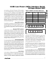
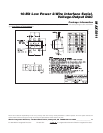
SCL
SDA
1
2
6
5
V
DD
ADD
GND
OUT
MAX5811
SOT23
TOP VIEW
3
4
Pin Configuration
Ordering Information
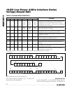
R
S
R
S
R
S
R
S
R
P
R
P
V
DD
µC
SDA
SCL
SDA
SDA
SCL
SCL
V
DD
V
DD
V
DD
OUT
OUT
MAX5811
MAX5811
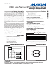
Typical Operating Circuit
19-2270; Rev 1; 11/04
For pricing, delivery, and ordering information, please contact Maxim/Dallas Direct! at
1-888-629-4642, or visit Maxim’s website at www.maxim-ic.com.
PART
TEMP RANGE
PIN-
PACKAGE
TOP
MARK
MAX5811LEUT-T
-40°C to +85°C
6 SOT23-6
AAYS
MAX5811MEUT-T
-40°C to +85°C
6 SOT23-6
AAYU
MAX5811NEUT-T
-40°C to +85°C
6 SOT23-6
AAYW
MAX5811PEUT-T
-40°C to +85°C
6 SOT23-6
AAYY
Functional Diagram appears at end of data sheet.
Rail-to-Rail is a registered trademark of Nippon Motorola, Ltd.
I
2
C is a trademark of Philips Corp.