


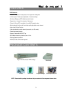
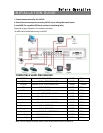
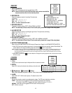
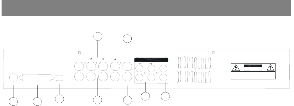
BACK PANEL
DVR
RISK OF ELECTRIC SHOCK
DO NOT OPEN
WARNING: TO REDUCE THE RISK OF ELECTRIC SHOCK,
DO NOT REMOVE COVER (OR BACK).
NO USER-SERVICEABLE PARTS INSIDE.
REFER SERVICING TO QUALIFIED
SERVICE PERSONNEL.
75Ω
HI
POWER
EXTERNAL I/O
INPUT
LOOP
CALL
2
MAIN
1
IN
L4
3
R
OUT
1
2
3
4
5
6
7
8
9
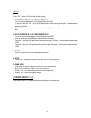
1. POWER
Please use the provided adapter to connect power cord (Other adapter is not suitable for this machine).
2. EXTERNAL I/O
‧Controlled remotely by an external device or control system.
‧Alarm input, external I / O explanation.
3. 75Ω / HI
When using Loop function, please switch to HI. If you don’t use Loop function or disconnect the video
input, please set it as 75Ω.
4. VIDEO INPUT (1-4)
Connect to video source, such as camera.
5. CALL
Connect to CALL monitor. Show the Switch Display.
When alarm trigger happens, the call monitor will show the triggered channel for a period of time.
6. AUDIO IN (1-4)
Connect to audio source, such as microphone.
‧IPS should be set to 25A (for NTSC) or 18A (for PAL)
✻ 4 audio inputs, but only can select 1 during recording.
7. AUDIO OUT (R/L)
Connect to monitor or speaker.
‧IPS should be set to 25A (for NTSC) or 18A (for PAL)
✻ with 2 mono audio outputs from the same source.
8. MAIN
Connect to Main monitor
9. LOOP (1-4)
Connect video signal between Input port and Loop port to make a loop.
7