


START THIS UNIT
Basic Operation
Before using the DVR, please have a HDD installed ready. (refer to Appendix #1 for installation or removal of a HDD).
Connect the AC Power Cord with Power Adapter and plug into an electrical outlet. The Red LED indicator light will be
ON and the DVR is in Standby mode.
1.
Press the Power button. The POWER LED will turn from red to orange, and other red LED indicators will turn ON. It
takes approximately 5 to 15 seconds to boot the system with the message : “ HDD Detecting ”. Once connected, the
POWER LED will change to green color, and the Alarm LED will be ON.
2.
3.
Before operating the DVR, please set up the system time first. (for setting system time, please refer to page.11).
NOTE : When “HDD not found” message shows up, please refer to appendix # 1. This indicates that the HDD
is not installed correctly.
OPERATION
RECORDING
The DVR offers a variety of recording modes, such as record continuously, at scheduled time, and by events. You can set
up recording speed and resolution. You can set these options by selecting MENU / RECORD before recording, please
refer to page.13. Under the recording status, if power is off accidentally, recorded video will still store in the HDD. DVR
will return to original recording situation after power returns again.
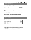
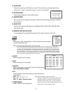
On the screen, you will find the date, time, HDD recording type, the amount of available GB left in the HDD memory and
the letter “A” represents the method of recording that is occurring.
(OW : HDD Overwrite)
NOTE : 1. When the HDD is full under O/W Recording mode, previous recorded files
may be overwritten without further warning notices.
2. If the HDDs’ capacity is only 5 GB left, it will buzz for 3 seconds; so as in 4GB, 3GB, 2GB and
1GB. If the O/W Recording mode(NOTE 1) is on, it won’t have the warning buzzer.
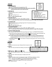
There are 4 recording modes in which Recording can occur : Alarm, Timer, Motion Trigger and Manual Record.
1. ALARM RECORD
DVR is triggered by an alarm input. Indicated by the letter “A” and show diagram on the triggered channel.
2. TIMER RECORD
Recording is scheduled by a Timer. Indicated by the letter “T”.
3. MANUAL RECORD
Recording is initiated by manually pressing the REC button. Indicated by the letter “M”.
4. MOTION TRIGGER RECORD
Recording is triggered by motion detection. Indicated by the letter “D” and show diagram on the triggered channel.
2002 – JAN –01 01:02:03
A●OW
8