


53
15. Connecting peripheral equipment
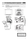
Connecting external
devices
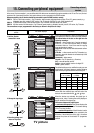
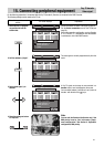
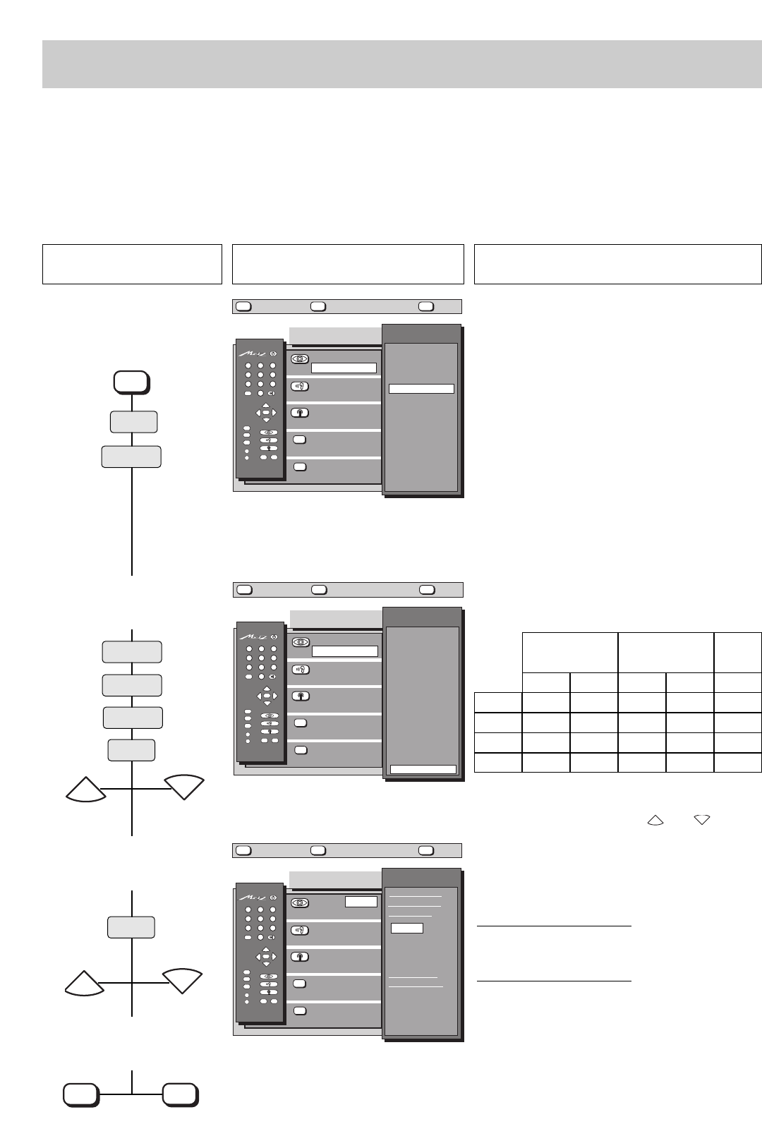
In the menu „Device connection“, you can define which AV devices are connected to the various sockets on the TV set. The box „Devices“
contains a list of common AV devices. Only certain devices can be connected to the FRONT sockets.
Wherever possible, the AV devices should be connected to specific EURO sockets, namely:
EURO 1: VHS or S-VHS video recorder + Pay-TV decoder, video recorder with data transfer to/from TV set, PC, games console ( e.g.
Nintendo), laser disk, photo CD, SAT receiver, Pay-TV decoder, SAT/Set Top unit, S-VHS playback unit.
EURO 2:
S-VHS/Hi8 video recorder, S-VHS/Hi8 video recorder + Pay-TV decoder, VHS video recorder, SAT receiver.
EURO 3:
VHS video recorder, VHS video recorder + Pay-TV decoder, games console (e.g. Nintendo), laser disk, photo CD, SAT receiver, Pay-TV decoder.
The connections are pre-programmed in the factory as shown in the picture for step 1.
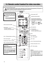
Press this key on the remote
control....
The screen displays Explanation
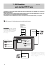
1. Call the „Device
connection“ menu
2. Change the device
connections
3. Change the signal type
4. Store the settings and
return to TV picture
OK
P
+
+
-
AV
--/-
-
P
123
456
789
0
A
B
TV
?
MENU
Device connection
Devices
▲
▼
697+05Q1-GB
AV
EURO2: Video
Video Rec. 2
EURO3: Video
Decoder A
Front: Video
Camcorder
Signal type
selection
?
MENU
return Help
TV
picture
no device
Video Rec. 1
Video Rec. 2
Video Rec. 3
LogicVTR
LogicVTR+D
VTR+DEC(1)
VTR+DEC(2)
VTR+DEC(3)
Camcorder
Mixer
PC
Decoder A
Decoder B
Laser Disk
Photo CD
SAT/SetTop
Games
EURO1: Video
LogicVTR+D
OK
P
+
+
-
AV
--/-
-
P
123
456
789
0
A
B
TV
?
MENU
Device connection
Devices
▲
▼
697+05R1-GB
AV
EURO2: Video
Video Rec. 2
EURO3: Video
Decoder A
Front: Video
Camcorder
Signal type
selection
?
MENU
return Help
TV
picture
no device
Video Rec. 1
Video Rec. 2
Video Rec. 3
LogicVTR
LogicVTR+D
VTR+DEC(1)
VTR+DEC(2)
VTR+DEC(3)
Camcorder
Mixer
PC
Decoder A
Decoder B
Laser Disk
Photo CD
SAT/SetTop
Games
EURO1: Video
Games
OK
P
+
+
-
AV
--/-
-
P
123
456
789
0
A
B
TV
?
MENU
Device connection
Sign. type
▲
▼
697+05S-GB
AV
EURO2: Video
Video Rec. 2
EURO3: Video
Decoder A
Front: Video
Camcorder
Signal type
selection
?
MENU
return Help
TV
picture
EURO1: Video
Games
Games
controls AV
operation
Video
RGB
YC in
continuous
AV operation
Video
RGB
YC in
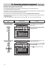
In the „Device connection“ menu, you can assign one
of the defined AV devices to each of the EURO sockets.
The abbreviations in the box on the right have the
following meanings:
Video rec. = video recorder (up to 3 may be connected).
Video rec. 1 is the video recorder which is always
connected; Video rec. 2 and 3 are used for copying
from one recorder to another.
Logic VTR = video recorder with data transfer to/from
the TV set
VTR+Dec. = video recorder and Pay-TV decoder (e.g.
Premiere), where the decoder is connected only to the
video recorder.
Camcorder = video camera
Decoder = Pay-TV decoder (e-g- Premiere)
SAT = external satellite receiver
SetTop =external satellite receiver for digital TV
Game = games console
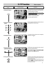
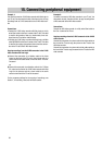
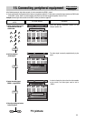
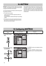
The default settings can be modified to meet your own
requirements. You should, however, note the following
input and output signal allocations when doing this.
To change the settings, select the appropriate EURO
socket with the coloured keys and then select the
device to be connected with the and keys.
P
-
P
+
When the devices are selected, the signal type is
always set to „video“. Pressing the red key displays a
box for selection of the signal type.
Differences between the signal types:
• continuous AV operation:
the screen displays the
picture provided by the AV device. The channel setting
of the TV set has no effect.
• . . . controls AV operation:
if the AV device is set to
„play“, the screen displays the picture provided by the
AV device; if the AV device is set to „stop“, the screen
displays the picture of the selected TV programme
position.
MENU
P
+
P
-
P
+
P
-
TV picture
OK
TV
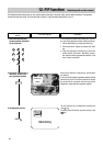
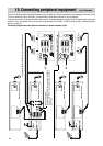
S-VHS / Hi8
(= Y/C =S-Video)
Input
EURO 1
EURO 2
EURO 3
FRONT
Output
VHS
(= Video)
Input Output
RGB
Input
Yes No Yes Yes Yes
Yes Yes Yes Yes No
No No Yes Yes Yes
Yes - Yes - No
red
yellow
red
yellow
blue
white
green