34
FX3S Series Programmable Controllers
User's Manual - Hardware Edition
4 Specifications, External Dimensions and Terminal Layout (Main Units)
4.5 Performance Specifications
4.5 Performance Specifications
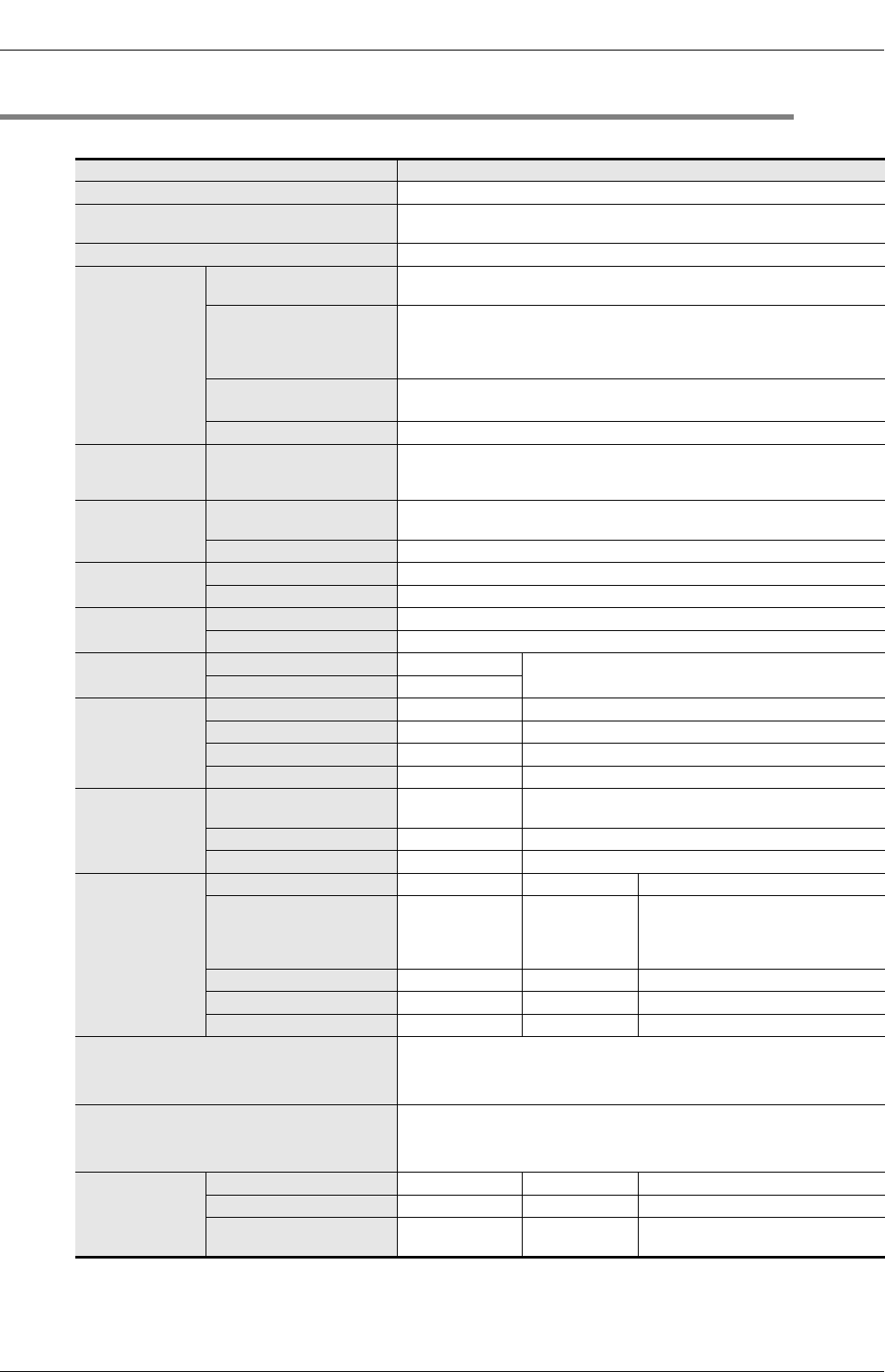
The performance specifications for the main unit are explained below.
Item Performance
Operation control system Stored program repetitive operation system with interruption function.
Input/output control system
Batch processing system (when END instruction is executed)
Input/output refresh instruction and pulse catch function are provided.
Programming language Relay symbol system + step-ladder system (SFC notation possible)
Program memory
Built-in memory capacity/type
16,000 steps/EEPROM memory (Program capacity is 4000 steps.)
Max. allowable write: 20,000 times
Memory cassette (Option)
32,000 steps/EEPROM memory (with loader function)
The FX3S Series PLC is available only to 16,000 steps. (Program capacity is 4000
steps.)
Max. allowable write: 10,000 times
Writing function during running
Provided (Program can be modified while the PLC is running.)
For the writing function during running, refer to Subsection 5.2.5.
Keyword function With keyword/Customer keyword function
Real-time clock
Clock function
*1
Built-in
1980 to 2079 (with correction for leap year)
2- or 4-digit year, accuracy within 45 seconds/month at 25 °C
Kinds of instructions
Basic instructions
Sequence instructions: 29
Step-ladder instructions: 2
Applied instructions 116 kinds
Processing speed
Basic instructions 0.21s/instruction
Applied instructions 0.5 s to several hundred s/instruction
Number of input/
output points
Input points 16 points or less (Extension is impossible.)
Output points 14 points or less (Extension is impossible.)
Input/output relay
Input relay X000 to X017
The device numbers are octal.
Output relay Y000 to Y015
Auxiliary relay
For general M0 to M383 384 points
EEPROM keep M384 to M511 128 points
For general M512 to M1535 1024 points
For special M8000 to M8511 512 points
State
For initial state
(EEPROM keep)
S0 to S9 10 points
EEPROM keep S10 to S127 118 points
For general S128 to S255 128 points
Timer
(on-delay timer)
100 ms T0 to T31 32 points 0.1 to 3,276.7 sec
100 ms/10 ms T32 to T62 31 points
0.1 to 3,276.7 sec/0.01 to 327.67 sec
When M8028 is driven ON, timers T32 to
T62 (31 points) are changed to 10 ms
resolution.
1 ms T63 to T127 65 points 0.001 to 32.767 sec
1 ms accumulating type T128 to T131 4 points 0.001 to 32.767 sec
100 ms accumulating type T132 to T137 6 points 0.1 to 3,276.7 sec
Variable analog potentiometers
Available as analog timers
VR1: D8030 VR2: D8031
For compatible PLCs, refer to Chapter 11.
Analog inputs
Available as voltage inputs
ch1: D8270 ch2: D8271
For compatible PLCs, refer to Chapter 11.
Counter
16 bits up (For general) C0 to C15 16 points Counting from 0 to 32,767
16 bits up (EEPROM keep) C16 to C31 16 points Counting from 0 to 32,767
32 bits up/down (For general) C200 to C234 35 points
Counting from -2,147,483,648 to
+2,147,483,647


