


18
19
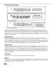
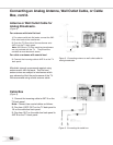
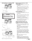
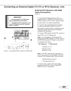
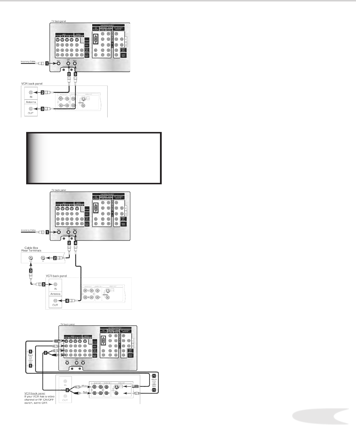
Connecting an Analog VCR
VCR to Analog Antennas or Wall
Outlet Cable (Figure 1)
1. Connect the incoming cable to ANT-A on the
TV back panel.
Note: Connect two coaxial cables as follows:
2. One from LOOP-OUT on the TV back panel
to ANTENNA IN on the VCR back panel.
3. One from VCR back panel ANTENNA OUT
to ANT-B on the TV back panel.
4. Now complete Figure 3, steps 1-2.
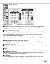
VCR to Cable Box (Figure 2)
1. Connect the incoming cable to ANT-A on the
TV back panel.
Note: Connect three coaxial cables as follows:
2. One from LOOP-OUT on the TV back panel
to IN on the back of the cable box.
3. One from OUT on the back of the cable box
to ANTENNA IN on the VCR back panel.
4. One from ANTENNA OUT on the VCR back
panel to ANT-B on the TV back panel.
5. Now complete Figure 3, steps 1-2.
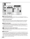
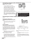
Adding Composite Video or an
S-Video with Audio Connections
(Figure 3)
1. Connect a video cable from VIDEO OUT on
the VCR back panel to VIDEO INPUT 1 on the
TV back panel.
Note: If you have an S-VHS VCR, follow the
same steps using the S-Video terminals on
the VCR and TV (in place of the composite
terminals).
2. Connect a set of audio cables from AUDIO
OUT on the VCR back panel to AUDIO INPUT 1
on the TV back panel. The red cable connects
to the R (right) channel and the white cable
connects to the L (left) channel. If your VCR is
mono (non-stereo), connect only the white (left)
cable.
Note: Step 2 allows the use of the TV
speakers with the VCR.
Important: If you add a second VCR or use
any other inputs for your VCR, see the section
on Editing NetCommand™ Setup to ensure this
change matches the NetCommand™ system.
Figure 3. Connecting the VCR Audio/Video.
Figure 2. Connecting VCR with cable box.
Figure 1. Connecting VCR with antennas or wall outlet
cable.
Additional connection cables are
not provided with the TV. They are
available at most electronic stores.
IMPORTANT