


In This Section . . .
Edit NetCommand™, cont’d.
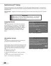
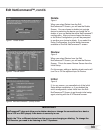
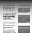
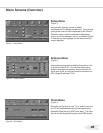
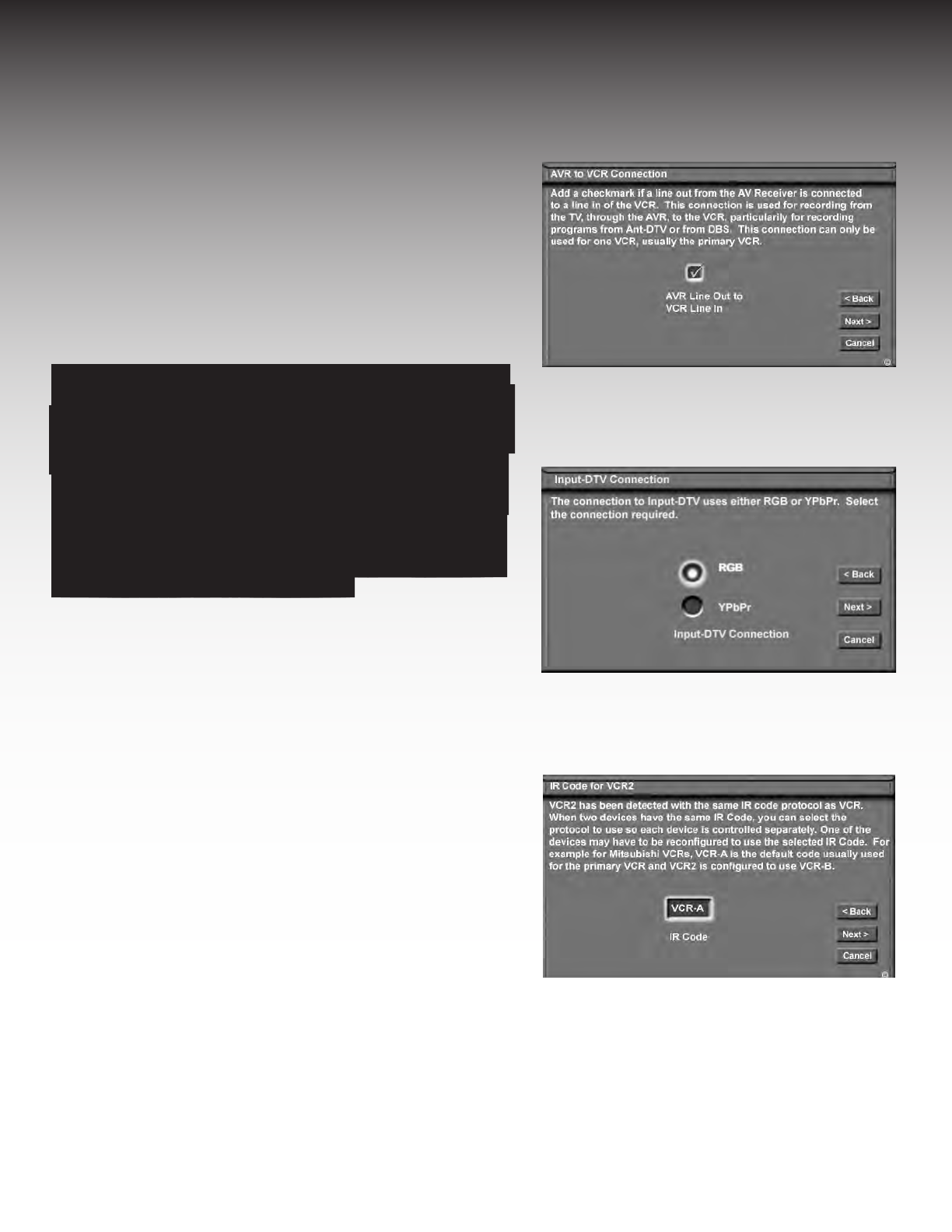
Figure 1. AVR to VCR Connection screen.
AVR to VCR Connection Screen
Figure 1
This screen is displayed only when a VCR is the
device being added or changed. The AVR to
VCR Connection screen allows you to conrm the
connection of the A/V Receiver’s record output
to the VCR’s line input. This connection allows
recording of signals from the TV Monitor output,
through the A/V Receiver, to analog VCR.
If you have more than one VCR, only one VCR can
be used for setup of recordings by NetCommand™.
This is also true when using both a legacy VCR
and the analog side of a DVCR. When connecting
cables from the AV Receiver to the VCR, take care
when selecting the VCR which will then be used
for all recordings by NetCommand™. Ensure that
this screen is correctly checked for the only device
connected to the AV Receiver.”
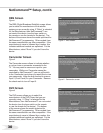
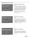
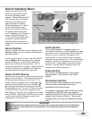
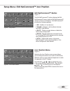
Figure 3. IR Code screen - (VCR2 example).
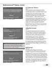
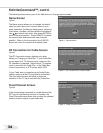
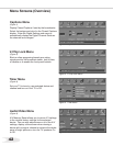
Figure 2. Input-DTV Connection screen.
Input-DTV Connection Screen
Figure 2
This screen displays only if the device selected in
the Connection screen is connected to Input-DTV.
The Input-DTV Connection screen allows you to
select which connection type, RGB or Component
Y/Pb/Pr you are using to connect your cable box,
DBS, or HDTV Receiver when connected to Input-
DTV.
IR Code for [Device] Screen
Figure 3
This screen only displays if a device added has the
same IR code as a device previously added. You
can specify the IR setting for the new device. For
example, for the second Mitsubishi VCR you can
specify the IR Code setting to VCR-B, if the primary
Mitsubishi VCR is using the VCR-A IR code.