


MODELS: WD-52627 / 52628 / 62627 / 62628 / 62827 / 62927 / 73727 / 73827 / 73927
Page 51
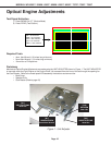
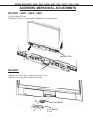
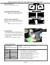
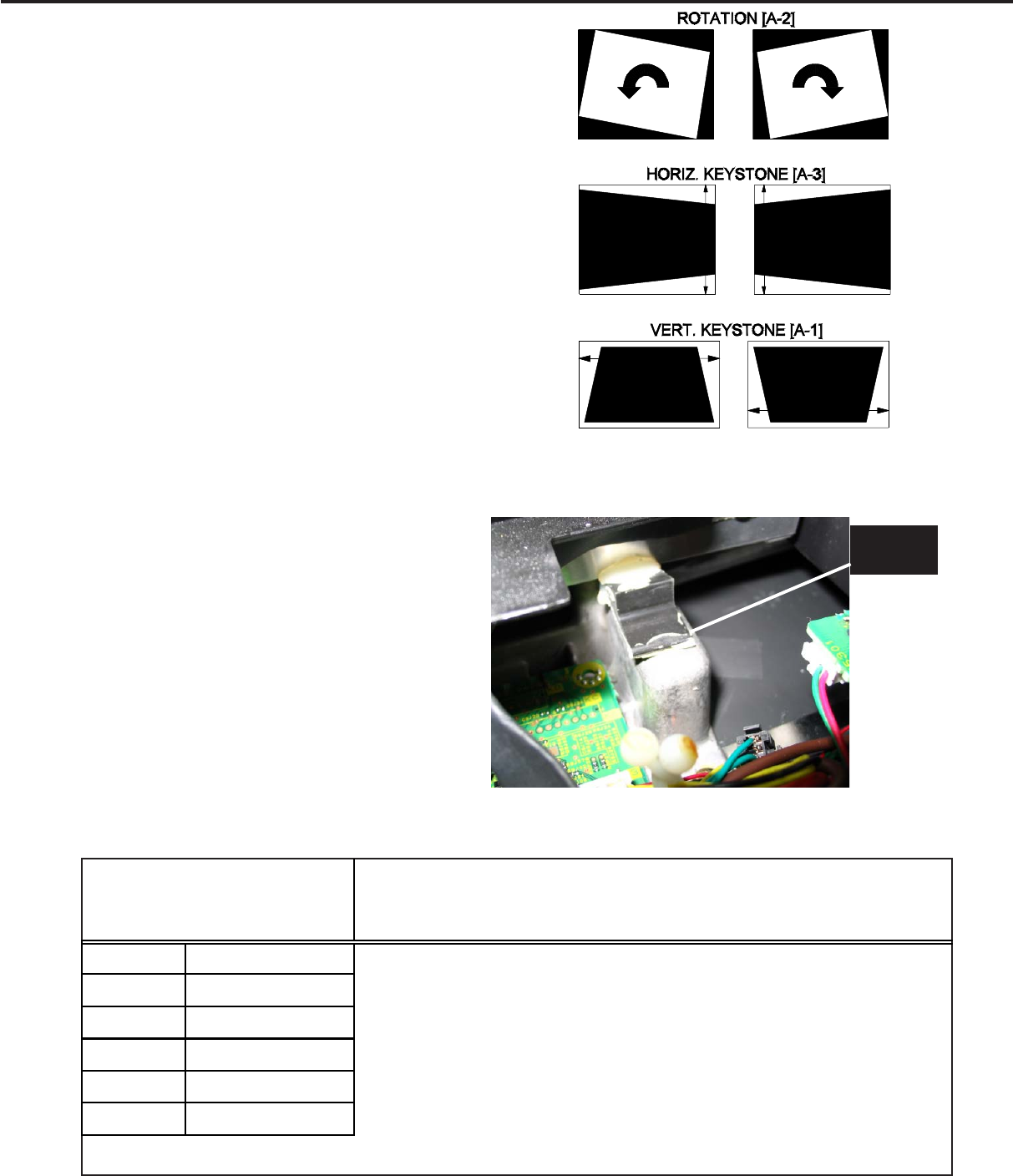
Rotation Adjustment
Adjust [A-2] to remove any picture rotation
Horizontal Keystone Adjustment
Adjust [A-3] to remove horizontal keystone distortion.
NOTE: Vertical Positioning may shift
Vertical Keystone Adjustment
Adjust [A-1- To remove vertical keystone distortion.
[A-1] can only be accessed by the front access hole
shown above.
NOTE: Horizontal Positioning may shift.
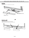
After Adjustment
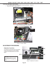
1) Slide the rubber wedge under the Engine slowly
until it make solid contact. (Figures Figures 3 & 6)
2) Tighten side Locking Screws [B-2]. (Figure 2)
3) Check the Picture, re-adjustment may be required
(usually rotation).
4) Tighten front Locking screw [B-1]. (Figure 3)
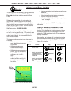
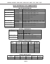
Purpose:
Measuring
Instrument
Test Point
Measuring
Range
Input Signal
Ext. Trigger
Input Terminal
Symptom:
[Format Circuit]
----
------
------
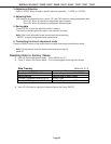
Internal Test Patern.
Video
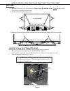
To center the picture on the screen.
Picture is off center.
1. Press “MENU-2-4-5-7”, activates the Service Mode..
2. Select the “FORMAT” function (AUDIO button).
3. Press “REWIND”, activates the Overscan Test Pattern
4. Select “Item 1” HPOS (VIDEO button).
5. Use the ADJUST buttons to center the picture horizontally.
6. Press ENTER to save the new setting.
7. Select “Item 2” VPOS (VIDEO button).
8. Use the ADJUST buttons to center the picture vertically.
9. Press ENTER to save the new setting.
10. Press MENU to exit the Service Mode.
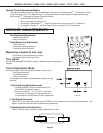
Horizont/Vertical Positi0n Adjust-
ment
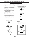
Figure 5: Adjustments
Electrical Adjustments
RUBBER
WEDGE
Figure 6: Wedge Insertion