


Chapter 2. TV Connections 25
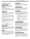
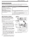
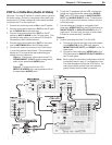
VCR to a Cable Box (Audio & Video)
Required: Two-way RF splitter, 4 coaxial cables, right and
left audio cables, S-Video or composite video cable, plus
component or S-Video cables and audio cables required
to connect the TV to the cable box.
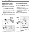
1. Connect the incoming cable to
IN
on the RF splitter.
2. Connect one coaxial cable from
OUT
on the RF split-
ter to
CABLE IN
on the cable box.
3. Connect one coaxial cable from
OUT
on the RF
splitter to
ANT 1/MAIN
on the TV back panel. This
connection also allows you to use the TV Guide On
Screen® and Split Screen features.
4. Connect one coaxial cable from
OUT
on the cable
box to
ANTENNA IN
on the VCR back panel.
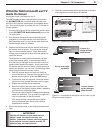
5. Connect the cable box outputs to the TV as shown
in one of the options listed below. This connection
allows the TV to receive the best available signal
directly from the cable box.
Figure 1: Component video output to the TV’s
COMPONENT Y Pb Pr
jacks; analog stereo
audio to the associated
AUDIO
jacks.
OR
Figure 2: S-Video output to the TV’s
INPUT/S-VIDEO
jack; analog stereo audio to
the associated
AUDIO
jacks.
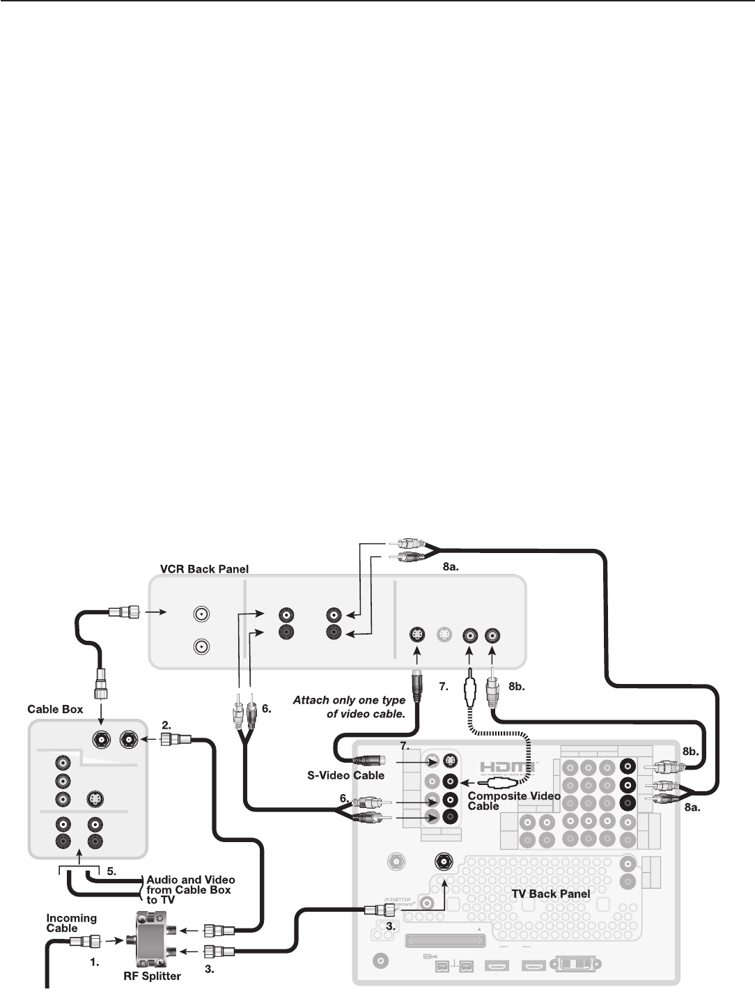
Figure 7. Connecting a VCR to a cable box
TM
R
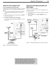
6. To use the TV speakers with the VCR, connect left
(white) and right (red) audio cables from
AUDIO
OUT
on the VCR back panel to
INPUT/AUDIO
LEFT
and
AUDIO RIGHT
on the TV back panel.
If your VCR is mono (non-stereo), connect only the
white (left) cable.
7. Connect either an S-Video or composite video
cable from
VIDEO OUT
on the VCR back panel to
INPUT/VIDEO
or
INPUT/S-VIDEO
on the TV
back panel. Connect only one type of video cable.
S-Video is recommended, if available.
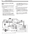
Optional
8. To allow recording from the TV to the VCR:
a. Connect left (white) and right (red) audio cables
from
AUDIO IN
on the VCR back panel to
MONITOR OUT/LEFT
and
RIGHT
on the TV
back panel.
b. Connect a video cable from
VIDEO IN
on the
VCR back panel to
MONITOR OUT/VIDEO
on
the TV back panel.
Note: When using this connection configuration with the
connections used in step 5, it is possible to view
live cable programs through the VCR Device. For
best picture quality always view live cable pro-
grams directly from the cable box device.