


22
22
Y
G
Pb
B
Pr
R
V
H
HIGH RESOLUTION INPUT
INPUT
3 PIP
S-VIDEO
VGA
640X 480, 60HZ
COMPONENT 480i /480p
1 (YPrPb)
2 (YPrPb)
DTV (YPrPb/GRBHV)
480i /480p /1080i
VIDEO
MONITOR
IR EMITTER HOME THEATER
21
STB
OUTPUT
AUDIO-
LEFT/
(MONO)
AUDIO-
RIGHT
AUDIO-
LEFT/
(MONO)
AUDIO-
RIGHT
ANT-BLOOP OUTANT-A
TV back panel
A/V Receiver
1
D IG ITA L
SURRO UND
S
CH
Other A/V Device
D IG ITA L
SURRO UND
S
CH
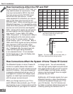
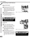
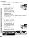
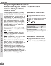
Figure 2. Connecting the System 4 Home Theater IR
Control.
See page 53 for details on using the
TV’s IR emitter to control a Mitsubishi
A/V receiver.
Part II: Installation
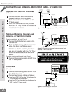
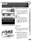
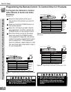
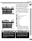
Connecting a Computer with a VGA Monitor Output
Connecting a Computer
(Figure 1)
1
Connect VGA Monitor Out from the com-
puter to VGA on the TV back panel
using a VGA compatible monitor cable.
See Appendix B, page 61, for VGA
signal compatability.
2
Connect the L (left) and R (right)
audio cables from the computer to VGA
AUDIO on the TV back panel. In cases
where your computer’s audio output is a
single mini-RCA jack, a spliter is needed
to complete this connection.
To utilize the bene ts of a digi tal A/V
receiver, connect your computer’s digital
audio out, if available, to a digital input
on your digital A/V receiver.
Figure 1. Connecting a computer with a VGA monitor
output.
Y
G
Pb
B
Pr
R
V
H
HIGH RESOLUTION INPUT
INPUT
3 PIP
S-VIDEO
VGA
640X480, 60HZ
COMPONENT
480i /480p
1 (YPrPb)
2 (YPrPb)
DTV (YPrPb/GRBHV)
480i /480p /1080i
VIDEO
MONITOR
IR EMITTER HOME THEATER
21
STB
OUTPUT
AUDIO-
LEFT/
(MONO)
AUDIO-
RIGHT
AUDIO-
LEFT/
(MONO)
AUDIO-
RIGHT
ANT-BLOOP OUTANT-A
AUDIO
VGA OUTPUT
L
R
VGA MONITOR
CABLE
VGA MONITOR
CABLE
White
Red
1
2
2
2
2
1
TV back panel
Computer with VGA Monitor Output.
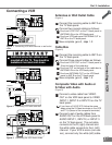
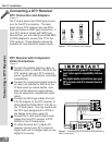
1
Connect the IR emitter to IR EMITTER
HOME THEATER on the TV back panel.
2
Place the IR emitter cable under or
along the side of the A/V device. Place
the IR lens directly in front of the A/V
device’s infrared signal receiver. Infra-
red signal receivers are usually behind
the front translucent panel of the device.
3
Place unused transmitters in an out-of-
the-way location.
4
For permanent installation of the IR
emitter cable, use the included adhesive
tape to secure the bottom of the emitter
to the anchoring object of your choice.
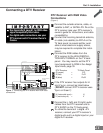
Connecting the System 4 Home Theater IR Control
(Figure 1)
Connecting a Computer and the System 4 Home Theater IR Control