


English-23
Operation - continued
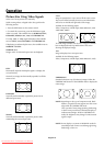
Creating a Video Wall
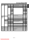
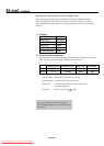
You can create a video wall consisting of up to 25 individual
monitors with the built-in matrix display capability. Your
Video Wall can have any of the following con gurations:
2x2, 3x3, 4x4, 5x5, 5x1, 4x1, 3x1, 2x1, 1x2, 1x3, 1x4, or 1x5.
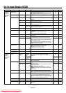
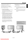
Connect the signal cables as shown:
1. Select VIDEO WALL in the OPTION 3 OSD menu, then
press the SET button.
2. Select the desired video wall con guration in the
DIVIDER eld.
3. Select POSITION in the VIDEO WALL menu, then press
the SET button. Appearing on the OSD is the current video
wall con guration. Select the position of the monitor for the
video wall.
NOTE: Each individual monitor within the video wall must
have its own set position.
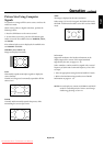
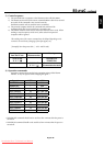
EXTERNAL CONTROL
OUT
IN
S-VIDEO IN
DVI AUDIO3
R
L
(MONO)
R
L
(MONO)
R
L
(MONO)
AUDIO2 AUDIO1VGA
HD VD
R/Cr/Pr G/Y B/Cb/pb
RGBHV / DVD/HD2
Y Cr/Pr Cb/Pb
DVD/HD1
IN
IN/OUT
VIDEO
AC IN
RL
SPEAKER (S)
Video Signal
RCA Phono Plug
(IN)
BNC connector
(OUT) to another
display
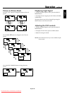
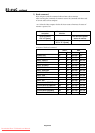
EXTERNAL CONTROL
OUT
IN
S-VIDEO IN
DVI AUDIO3
R
L
(MONO)
R
L
(MONO)
R
L
(MONO)
AUDIO2 AUDIO1VGA
HD VD
R/Cr/Pr G/Y B/Cb/pb
RGBHV / DVD/HD2
Y Cr/Pr Cb/Pb
DVD/HD1
IN
IN/OUT
VIDEO AC IN
RL
SPEAKER (S)
RGB/DVD/HD Signal
BNC connector
(IN)
VGA connector
(OUT) to
another
display
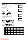
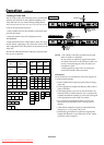
NO. 16 NO. 17 NO. 18 NO. 19
NO. 20 NO. 21 NO. 22 NO. 23
NO. 24 NO. 25 NO. 26 NO. 27
NO. 28 NO. 29 NO. 30 NO. 31
NO. 5NO. 4NO. 3NO. 1 NO. 2
NO. 32 NO. 33 NO. 34 NO. 35 NO. 36
NO. 37 NO. 38 NO. 39 NO. 40 NO. 41
NO. 42 NO. 43 NO. 44 NO. 45 NO. 46
NO. 47 NO. 48 NO. 49 NO. 50 NO. 51
NO. 52 NO. 53 NO. 54 NO. 55 NO. 56
NO. 7 NO. 8 NO. 9
NO. 10 NO. 11 NO. 12
NO. 13 NO. 14 NO. 15
NO. 1 NO. 2
NO. 4 NO. 3
2 x 2 3 x 3
4 x 4 5 x 5
5 x 1
NO. 4NO. 3
NO. 3
NO. 1 NO. 2
4 x 1
NO. 1
NO. 2
NO. 3
NO. 4
NO. 5
1 x 5
NO. 1
NO. 2
3 x 1
NO. 1 NO. 2
2 x 1
NO. 1
NO. 2
NO. 3
NO. 4
1 x 4
NO. 1
NO. 2
NO. 3
1 x 3
NO. 1
NO. 2
1 x 2
Video Wall Confi gurations
NOTE: 1. e VIDEO 1 and VGA terminals may be used
either for INPUT or OUTPUT.
Do not connect an OUTPUT signal from another
unit when LOOP OUT in the OPTION 3 OSD is set
to ON, as it may damage the other unit due to an
extraordinary load.
2. While signals are input to the VGA terminal,
LOOP OUT should not be turned ON.
Information:
Set the LOOP OUT in OPTION3 to ON to loop signals out
to another plasma display.
Set the VIDEO WALL options properly when creating a
video wall.
Use the appropriate (length and e ciency) BNC cable to
connect monitors.
If the image quality is poor, do not use the monitor out
terminal to link to another monitor. Use a commercially
available distribution ampli er to connect the split signal
to the appropriate monitor INPUT terminals.
For a resolution of 1024x768 at 60 Hz (or lower), the
maximum recommended size for a viewing wall is 4
displays.
A distribution ampli er is highly recommended when
setting up a 3 x 3 (or greater) video wall.
When looping from plasma to plasma, an appropriate
(length and e ciency) 15-pin male mini D-Sub - 5BNC
conversion cable is required.
•
•
•
•
•
•
Downloaded From TV-Manual.com Manuals