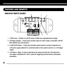
5. Status/IR Confirmation LED – This LED performs two functions: (1) it provides a
visible indication of system status via a green LED and (2) confirms the reception of IR
data via a blinking blue LED
6. Flasher Hi/Lo switch – Setting these switches to the appropriate position allows you to
connect either a high output flooding flasher (IRB1) or low output microflashers (MF1,
MF1VF, MF2, MF2VF)
7. Sensor Input – Removable quick connect sensor plug for connection of IR sensors to the
system
INSTALLATION CONSIDERATIONS
PLACEMENT OF THE MSU250
Place the MSU250 conveniently close to the equipment it will be controlling. Generally, the unit is
placed in a concealed location because its controls and indicators are only used during installation.
Placement possibilities include:
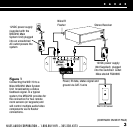
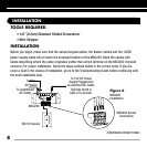
1) Table-top (on the floor or shelf behind the equipment (Figure 2)
2) Wall-mount (affixed to the back of the equipment cabinet or a nearby wall (Figure 3)
NILES AUDIO CORPORATION – 1-800-BUY-HIFI – 305-238-4373
5
5
(CONTINUED ON NEXT PAGE)
Figure 3
Wall-mount
placement
Use sheetrock
screws.
Figure 2
Table-top
placement
Affix the enclosed self-adhesive
rubber feet to the base of the
MSU250.
Self-Adhesive Rubber Feet
MSU250 Base
FEATURES AND BENEFITS


