


DIGITAL
AUDIO OUT
COAXIAL
ANT-OUT
ANT-IN
ANT-OUT
ANT-IN
AUDIO
OUT
DVD VCR
DVD/VCR
S-VIDEO
OUT
COMPONENT
VIDEO OUT
AUDIO IN
VIDEO IN
AUDIO OUT
VIDEO OUT
L
LYL
RR
R
C
B
/
P
B
C
R
/
P
R
DIGITAL
AUDIO OUT
COAXIAL
AUDIO
OUT
DVD
DVD/VCR
VCR
S-VIDEO
OUT
COMPONENT
VIDEO OUT
AUDIO OUT
VIDEO OUT
AUDIO IN
VIDEO IN
L
L
Y
C
B
/
P
B
C
R
/
P
R
L
R
R
R
–
7
–
EN
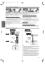
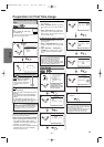
Setup
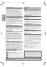
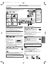
AUDIO IN jacks
Connect audio cables coming
from the audio out jacks of a
camcorder, another VCR, or an
audio source here.
DVD ANALOG AUDIO OUT
jacks
Connect the supplied audio
cables here through the Audio
In jacks of a television or other
audio equipment. (DVD only)
DVD/VCR AUDIO OUT jacks
Connect the supplied audio
cables here through the audio
In jacks of a television or other
audio equipment.
ANT IN jack
Connect your antenna
or cable box here.
ANT OUT jack
Connect the
supplied RF
cable to the
antenna input
jack on your TV.
DVD/VCR VIDEO OUT jack
Connect the supplied yellow
video cable here through
the TV’s video in jack.
COAXIAL jack
Connect an optional coaxial
digital audio cable here
through the coaxial digital
audio in jack of a decoder or
audio receiver. (DVD only)
VIDEO IN jack
Connect a cable com-
ing from the video out
jack of a camcorder,
another VCR, or an
audio-visual source
(laser disc player, video
disc player, etc.) here.
S-VIDEO OUT jack
Connect an optional
S-Video cable here
through the S-video
in jack of a televi-
sion. (DVD only)
COMPONENT VIDEO
OUT jacks
Connect optional component
video cables here through
the component video in
jacks of a television.
(DVD only)
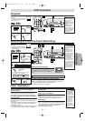
Front & Rear Terminals
DIGITAL
AUDIO OUT
COAXIAL
ANT-OUT
ANT-IN
AUDIO
OUT
DVD VCR
DVD/VCR
S-VIDEO
OUT
COMPONENT
VIDEO OUT
AUDIO IN
VIDEO IN
AUDIO OUT
VIDEO OUT
L
LY
C
B/
P
B
C
R/
P
R
L
RR
R
AUDIO IN
LR
VCRDVD/VCR
AUDIO IN
VIDEO IN
AUDIO OUT
VIDEO OUT
L
L
R
R
DIGITAL
AUDIO OUT
COAXIAL
AUDIO
OUT
DVD
S-VIDEO
OUT
COMPONEN
VIDEO OUT
L
R
or
VIDEO IN
VCRDVD/VCR
AUDIO IN
VIDEO IN
AUDIO OUT
VIDEO OUT
L
L
R
R
S-VIDEO IN
DIGITAL
AUDIO OUT
COAXIAL
AUDIO
OUT
DVD
S-VIDEO
OUT
COMPONENT
VIDEO OUT
L
R
Y
C
B/
P
B
C
R/
P
R
DIGITAL
AUDIO OUT
CB
Y
C
R
COMPONENT
VIDEO IN
or
COAXIAL
AUDIO
OUT
DVD
S-VIDEO
OUT
COMPONENT
VIDEO OUT
L
R
Y
C
B/
P
B
C
R/
P
R
PB
Y
P
R
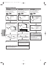
(Analog) AUDIO OUT
VIDEO OUT
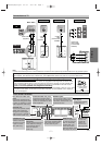
TV
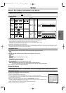
Method 1
Good pictureBasic Audio
Method 2 Method 3
Better picture Best picture
S-VIDEO OUT
COMPONENT VIDEO OUT
Video
cable
(supplied)
Audio cable
(supplied)
S-Video
cable
(commercially
available)
Component
Video cables
(commercially
available)
Note
•
Connect this unit directly to the TV. If the A/V cables are connected to a VCR, pictures may be distorted due to the copy protection system.
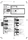
DVD/VCR
Connection to a TV
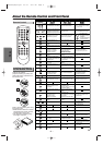
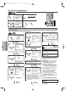
If your TV is compatible with progressive scanning 525p (480p) and you want to
enjoy that high quality picture;
You must select the connection Method 3 above and progressive scanning mode. To set the mode,
press and hold the PLAY button on the front panel for more than 5 seconds, so that “P.SCAN” will
appear on the display of this unit. (The progressive scanning is not available in the VCR mode.)
If your TV is not compatible with progressive scanning;
Use this unit in interlace mode. Make sure that no “P.SCAN” is on the display of this unit. If not, press
and hold the PLAY button on this unit for more than 5 seconds, so that “P.SCAN” on the display of
this unit will disappear.
STOP
OUTPUT
DVD
PLAY
VCR
STOP/EJ
E
POWER
F.F WDREW
V
ID
E
O
-- A
U
D
IO
--
L
R
/
more than 5 seconds
[Interlace mode]
[Progressive scanning mode]
[DVD/VCR]
[Back of DVD/VCR]
[Front of
DVD/VCR]
•
When progressive scanning mode is selected, no video signal will be output from the VIDEO OUT or S-VIDEO OUT jacks.
•
The COAXIAL,
DVD AUDIO OUT,
S-VIDEO OUT, and COMPONENT VIDEO OUT jacks are only useful in DVD mode.
H9603CD(EN)v1.qx3 04.3.1 9:57 PM Page 7