


3-1 L6115STA
STANDARD NOTES FOR SERVICING
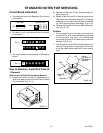
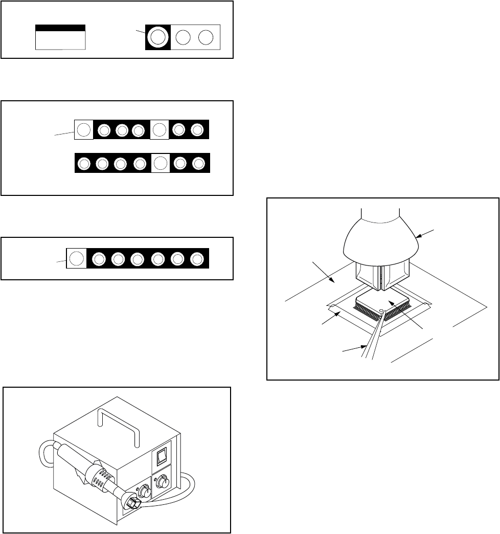
Circuit Board Indications
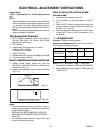
a. The output pin of the 3 pin Regulator ICs is indicat-
ed as shown.
b. For other ICs, pin 1 and every fifth pin are indicat-
ed as shown.
c. The 1st pin of every male connector is indicated as
shown.
How to Remove / Install Flat Pack-IC
1. Removal
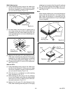
With Hot-Air Flat Pack-IC Desoldering Machine:
(1) Prepare the hot-air flat pack-IC desoldering ma-
chine, then apply hot air to the Flat Pack-IC (about
5 to 6 seconds). (Fig. S-1-1)
(2) Remove the flat pack-IC with tweezers while ap-
plying the hot air.
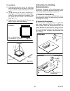
(3) Bottom of the flat pack-IC is fixed with glue to the
CBA; when removing entire flat pack-IC, first apply
soldering iron to center of the flat pack-IC and heat
up. Then remove (glue will be melted). (Fig. S-1-6)
(4) Release the flat pack-IC from the CBA using twee-
zers. (Fig. S-1-6)
Caution:
1. Do not supply hot air to the chip parts around the
flat pack-IC for over 6 seconds because damage
to the chip parts may occur. Put masking tape
around the flat pack-IC to protect other parts from
damage. (Fig. S-1-2)
2. The flat pack-IC on the CBA is affixed with glue, so
be careful not to break or damage the foil of each
pin or the solder lands under the IC when remov-
ing it.
Top View
Out
In
Bottom View
Input
5
10
Pin 1
Pin 1
Fig. S-1-1
Hot-air
Flat Pack-IC
Desoldering
Machine
CBA
Flat Pack-IC
Tweezers
Masking
Tape
Fig. S-1-2