Parts and their functions
6 (E)
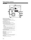
1 HD SDI IN connector (BNC)
The HD SDI signals are supplied to this connector.
2 HD SDI through connector (BNC)
The HD SDI input signals are passed straight through the
unit and output here.
3 HD SDI OUT connector (BNC)
The HD SDI signals are output from this connector.
4 REMOTE IN (RS-422) connector
The remote controller is connected to this connector.
The only commands supported in the remote control
mode are FF, REW, STOP, PLAY, REC and SHTL.
<Note>
Functions that cannot be used when an external control
unit is used
OClip location function initiated by pressing the SHIFT
key and FF or REW key at the same time
OEject control function initiated by pressing the SHIFT
key and REW key on the remote controller (AJ-A95)
5 SD OUT VIDEO connector
The down-converted signals are output from this connec-
tor.
6 AC IN socket
The power cord is connected to this socket.
7 FUSE holder
This contains a 3.15A fuse.
8 SIGNAL GND
To minimize noise, this is connected to the signal ground
on the component connected. It is not a safety ground.
9 Fan motors
These are used to cool down the unit.
123
5
4
6
7
8
9
REMOTE IN
SD OUT
HD SDI
VIDEO
IN
ACTIVE
THROUGH
OUT
AC IN
~
SIGNAL
GND
F
U
S
E
P
U
S
H
Rear panel


