


14
RQT8881
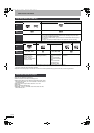
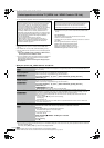
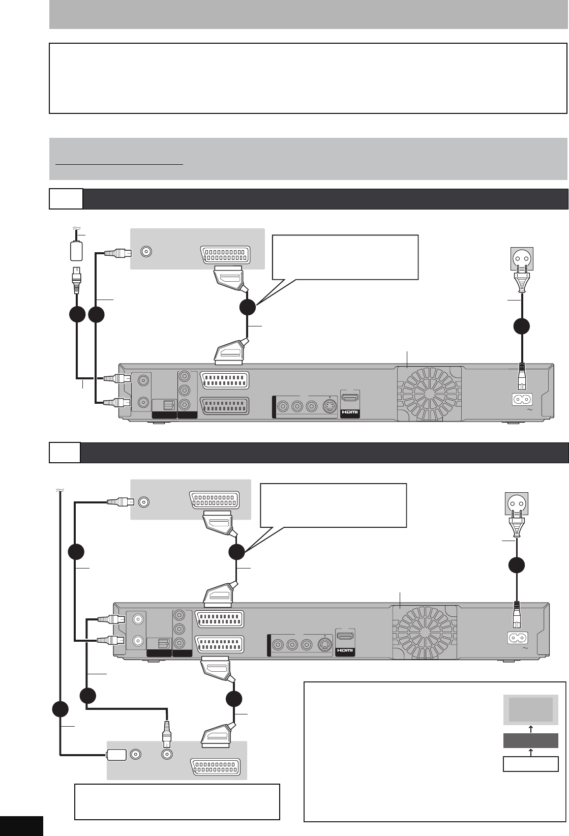
STEP 1 Connection
≥Before connection, turn off all equipment and read the appropriate operating instructions.
≥
Select the connection pattern that matches your environment from pattern A–D. Confirm connections not listed below with your dealer.
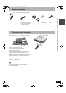
Make sure to use the pair of supplied RF coaxial cables
Use the pair of supplied RF coaxial cables only when you make connections to the unit through its RF IN and RF OUT terminals. Striping may
appear and disrupt images on the TV if you use different cables for connection.
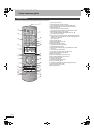
Using a 21-pin Scart cable
≥You can use a variety of Q Link functions by connecting the unit to a Q Link compatible television (➡ 18).
≥You can enjoy high-quality viewing by connecting the unit to an RGB compatible television (➡ 81).
[Required]setting] “AV1 Output” in the Setup menu (➡ 65)
When the unit is not to be used for a long time
To save power, unplug it from the household mains socket. This unit consumes a small amount of power, even when it is turned off
[approx. 2 W (Power Save mode)]
When “Power Save” is set to “On”, the “Quick Start” function does not work.
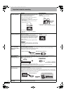
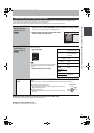
A
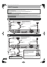
Connecting a television
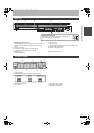
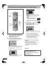
B
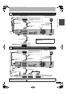
Connecting a television and VCR
RF
RF
IN
IN
RF
RF
OUT
OUT
AV2
(
DECODER/EXT
)
AV1
(
TV
)
OPTICAL
DIGI
DIGIT
AL
AL A
UDIO OU
UDIO OUT
(PCM/BITSTREAM)
(PCM/BITSTREAM)
COMPONENT
COMPONENT
VIDEO OUT
VIDEO OUT
S VIDEOVIDEO
R-AUDIO-L
PR
PB
Y
AC IN
OUT
OUT
A
A
V OU
V OU
T
T
VHF/UHF
RF IN
AV
4
3
2
1
2
To the aerial
Television’s rear panel
Aerial
cable
RF coaxial
cable (included)
This unit’s rear panel
To household mains socket
(AC 220 to 240 V, 50 Hz)
Fully wired 21-pin
Scart cable
AC mains lead
(included)
Connect only after all other
connections are complete.
Cooling fan
Connecting a terminal other
than the 21-pin Scart terminal
(➡ 16, 17)
RF coaxial
cable
(included)
RF
RF
IN
IN
RF
RF
OUT
OUT
AV2
(
DECODER/EXT
)
AV1
(
TV
)
OPTICAL
DIGI
DIGIT
AL
AL A
UDIO OU
UDIO OUT
(PCM/BITSTREAM)
(PCM/BITSTREAM)
COMPONENT
COMPONENT
VIDEO OUT
VIDEO OUT
S VIDEOVIDEO
R-AUDIO-L
P
R
P
B
Y
AC IN
OUT
OUT
A
A
V OU
V OU
T
T
3
1
AV
VHF/UHF
RF IN
VHF/UHF
RF IN
AV OUT
5
RF OUT
6
2
2
4
To the aerial
Aerial cable
Cooling fan
RF coaxial cable
(included)
This unit’s rear panel
To household mains socket
(AC 220 to 240 V, 50 Hz)
Television’s rear panel
VCR’s
rear panel
AC mains lead
(included)
Connect only after all other
connections are complete.
RF coaxial cable
(included)
Connecting a terminal other
than the 21-pin Scart
terminal (➡ 16, 17)
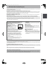
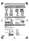
Connect the unit directly to the television
If you connect the unit through an AV selector
or video cassette recorder to the television,
video signal will be affected by copyright
protection systems and the picture may not
be shown correctly.
Fully wired 21-pin
Scart cable
21-pin Scart
cable
Television
VCR
This unit
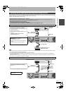
≥When connecting to a television with a built-in VCR
Connect to the input terminals on the television side if there are
both television and VCR input terminals.
[Required]setting]
“AV2 Input” and “AV2 Connection” settings in the Setup
menu (➡ 66)
DO NOT
EH575.book Page 14 Tuesday, January 30, 2007 10:30 AM