


16
RQT8881
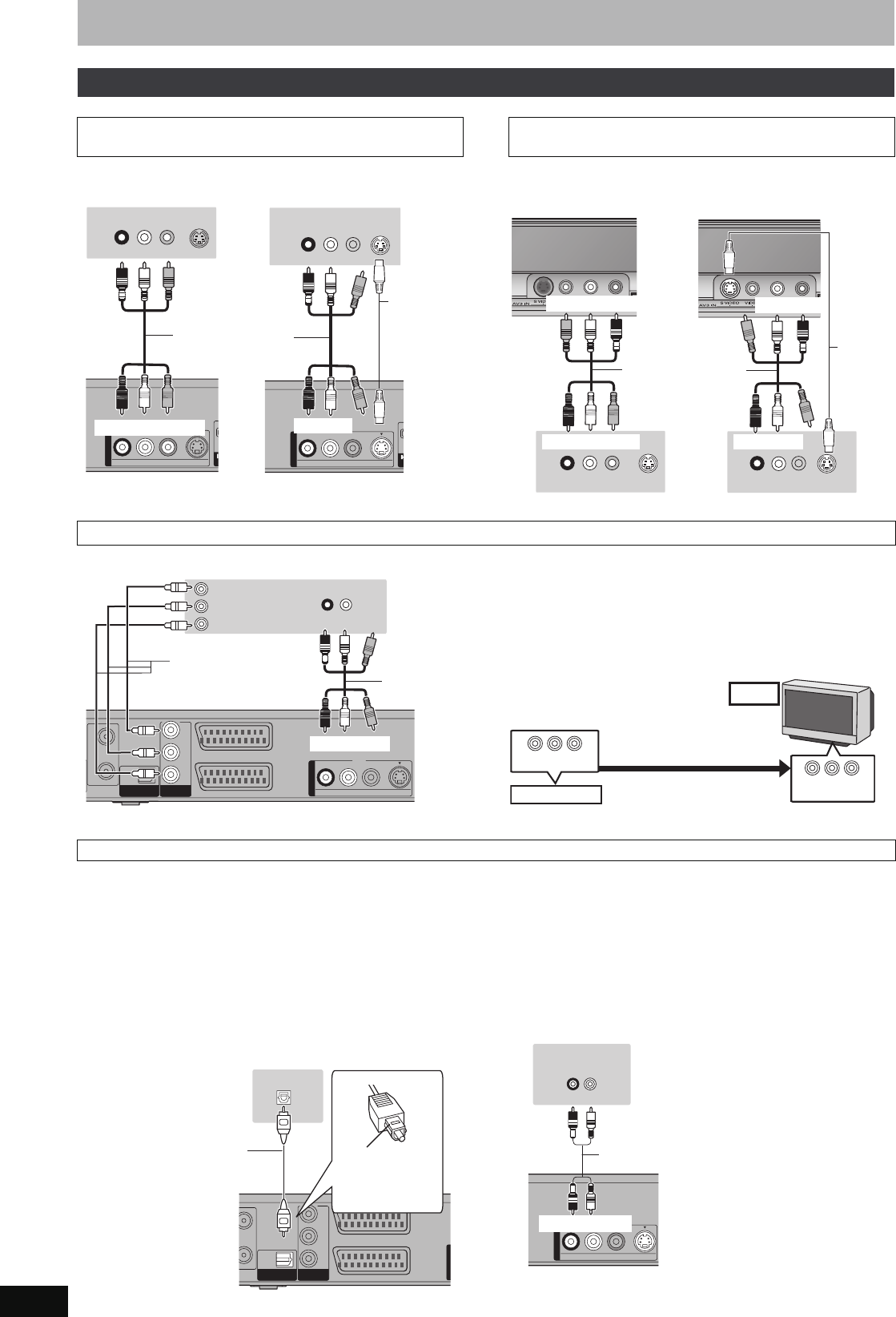
STEP 1 Connection
§
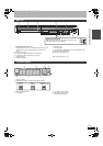
Leave “Yellow” unconnected.
The S VIDEO OUT terminal achieves a more vivid picture than the
VIDEO OUT terminal. (Actual results depend on the television.)
The S VIDEO terminal achieves a more vivid picture than the VIDEO
terminal. (Actual results depend on the television.)
COMPONENT VIDEO terminals can be used for either interlace or
progressive output (➡ 81) and provide a purer picture than the S
VIDEO OUT terminal.
≥Connect to terminals of the same colour.
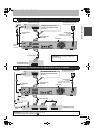
If you have a regular television (CRT: cathode ray tube)
Use component output with progressive “Off” (The default setting
➡ 65), even if it is progressive compatible, because progressive
output can cause some flickering. This is the same for multi system
televisions using PAL mode.
For progressive output (➡ 24)
∫
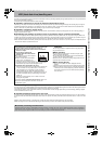
Connecting an amplifier with a digital input terminal
≥To enjoy multi-channel surround sound DVD-Video, connect an
amplifier with Dolby Digital, DTS and MPEG decoders.
[Required]setting]
“Digital Audio Output” in the Setup menu (➡ 64)
≥When this unit is connected to an amplifier with an Optical digital
audio cable and connected to a television with an HDMI cable, you
can enjoy the highest quality of audio from the disc by setting
“Digital Audio Output” to “Optical Only” in the Setup menu (➡ 65).
In this case audio is only output from the amplifier not the
television.
≥Before purchasing an optical digital audio cable (not included),
check the terminal shape of the connected equipment.
≥You cannot use DTS Digital Surround decoders not suited to DVD.
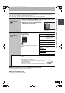
∫ Connecting a stereo amplifier
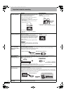
Other connections
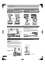
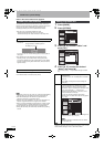
Connecting a television with AUDIO/VIDEO or
S VIDEO terminals
S VIDEOVIDEO
R-AUDIO-L
OUT
OUT
AV O
S VIDEO
IN
AUDIO IN
R L
VIDEO
IN
S VIDEOVIDEO
R-AUDIO-L
OUT
OUT
AV O
S VIDEO
IN
AUDIO IN
R L
VIDEO
IN
§
§
Red White Yellow
Red White Yellow
This unit’s rear panel
Audio/Video cable
(included)
Television’s rear panel Television’s rear panel
Red White
S Video
cable
Red White
This unit’s rear panel
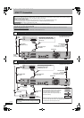
Connecting a VCR with AUDIO/VIDEO or
S VIDEO terminals
R L
AUDIO OUT
VIDEO
OUT
S VIDEO
OUT
R L
AUDIO OUT
VIDEO
OUT
S VIDEO
OUT
§
§
This unit’s front panel
Red White Yellow
Yellow White Red
Audio/Video cable
(included)
VCR’s rear panel
This unit’s front panel
S Video
cable
VCR’s rear panel
White Red
Red White
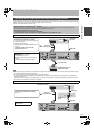
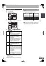
Connecting a television with COMPONENT VIDEO terminals
RF
RF
IN
IN
RF
RF
OUT
OUT
AV2
(
DECODER/EXT
)
AV1
(
TV
)
OPTICAL
DIGI
DIGIT
AL
AL A
UDIO OU
UDIO OUT
(PCM/BITSTREAM)
(PCM/BITSTREAM)
COMPONENT
COMPONENT
VIDEO OUT
VIDEO OUT
S VIDEOVIDEO
R-AUDIO-L
PR
PB
Y
OUT
OUT
AUDIO IN
R L
PR
PB
Y
COMPONENT
VIDEO IN
§
§
Red White
Red White
Video cable
Audio/Video
cable
(included)
Television’s rear panel
This unit’s rear panel
COMPONENT VIDEO OUT
COMPONENT
VIDEO IN
CRT
This unit
Progressive output
DO NOT
Connecting an amplifier or system component
UT
AV2
(
DECODER/EXT
)
AV1
(
TV
)
OPTICAL
DIGI
DIGIT
AL
AL A
UDIO OU
UDIO OUT
(PCM/BITSTREAM)
(PCM/BITSTREAM)
COMPONENT
COMPONENT
VIDEO OUT
VIDEO OUT
PR
PB
Y
OUTOUT
OPTICAL IN
Optical digital audio cable
Do not bend sharply when
connecting.
This unit’s rear panel
Insert fully, with
this side facing
up.
Amplifier’s rear panel
S VIDEOVIDEO
R-AUDIO-L
OUT
OUT
AUDIO IN
R L
Red White
Red White
Audio cable
This unit’s rear panel
Amplifier’s rear panel
EH575.book Page 16 Tuesday, January 30, 2007 10:30 AM