


35
Basic Operation
VCR
DVD player
This equipment can
also be con nect ed to
the rear terminals. See
Connections for details.
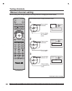
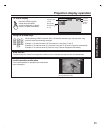
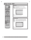
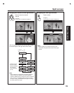
Turning the power on and switching input modes
Turn the projection
display on.
1
2
The input mode changes
each time this button is
pressed.
* If SKIP is set as the Input
Label setting of SETUP, the
mode will not be changed.
(P. 52)
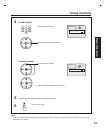
3
Operate the connected equipment.
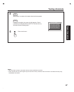
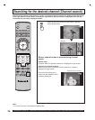
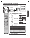
Confirming connections
A video camera uses the Input 3 terminal on the front of the projection display.
Video camera
To S-video output
or video output
To audio output
Example: Connect Input 3
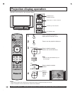
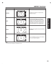
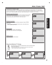
VIDEO 1 Signal of source connected to INPUT 1 is displayed.
VIDEO 2 Signal of source connected to INPUT 2 is displayed.
VIDEO 3 Signal of source connected to INPUT 3 is displayed.
COMPONENT 1
Signal of source connected to COMPONENT VIDEO INPUT 1 is displayed.
COMPONENT 2
Signal of source connected to COMPONENT VIDEO INPUT 2 is displayed.
COMPONENT 3
Signal of source connected to COMPONENT VIDEO INPUT 3 is displayed.
COMPONENT 4
Signal of source connected to COMPONENT VIDEO INPUT 4 is displayed.
RGB 1 (or RGB)
Signal of source connected to RGB IN 1 (or RGB IN) is displayed.
RGB 2 Signal of source connected to RGB IN 2 is displayed.
HDMI Signal of source connected to HDMI IN is displayed.
CARD Signal of source connected to CARD SLOT is displayed.
TV
VIDEO 1 *
VIDEO 2 *
VIDEO 3 *
COMPONENT 1 *
COMPONENT 2 *
HDMI*
COMPONENT 4 *COMPONENT 3 *
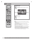
Card input mode is
selected.
Playing peripheral equipment
RGB 2*
(For PT-50LC14/ PT-60LC14)
RGB 1*
(For PT-50LC14/PT-60LC14)
RGB*
(For PT-43LC14)
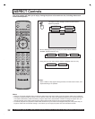
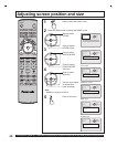
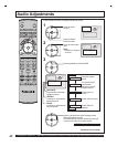
Remote Control
Unit
POWER
SAP
LIGHT
MENU
123
456
78
0
9
EXIT
CH
CH
VOL VOL
R-TUNE
SWAP
REW
FREEZE
TV/VCR
SPLIT CH
DVD/VCR CH
SEARCH
OPEN/CLOSE
SPLIT
PLAY
PAUSE STOP REC
SPLIT CTRL
FF
PROG
TV/VIDEO
A -ANTENNA- B
TV VCR DVD
DTV RCVR
DBS/CBL
AUX
OK
M
U
T
E
A
S
P
E
C
T
B
B
E
R
E
C
A
L
L
• Pressing SD again exits
Card input mode.