


8
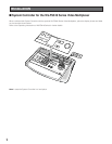
!8 Decrement Button (DEC –1CAM)
When a sequence running in forward direction has
been paused with the STOP button, pressing this button
will move the sequence one frame to the previous step
(in forward run direction). If the sequence was running
in reverse direction, the button will move the sequence
one frame to the previous step (in reverse run direc-
tion).
This button is also used to select a camera. Pressing
this button will replace the currently selected camera
with the next lower camera number, if the active monitor
is in Spot mode.
!9 Auxiliary Button (AUX 1, 2)
These buttons toggle the auxiliary switches in the
Receiver on and off.
The auxiliary switches can be used, for example, to
activate equipment connected to the receiver, such as
lamps and buzzers.
@0 Alternate Button (ALT)
This button activates the alternate function of dual-func-
tion control buttons.
@1 Forward Sequence Button (FORWARD SEQ)
This button is used to run a selected Program or Tour
Sequence in forward direction on the active monitor.
It also restarts a sequence forward from the step that
was previously paused by pressing the Stop button.
@2 Backward Sequence Button (BACK SEQ)
This button is used to restart a sequence backward
from the step that was previously paused by pressing
the Stop button.
@3 Alarm Acknowledge and Reset Button (ACK RESET)
This button cancels an activated alarm. To cancel an
alarm, first select the alarmed monitor(s), then press the
ACK RESET button once for alarm acknowledgment
(the indicator on the button blinks rapidly), and finally
press it again for alarm reset (the indicator goes off).
After an alarm acknowledgment, pressing this button
while the Alternate (ALT) indicator is on will cancel all
currently activated alarms at the same time.
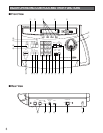
@4 Data Ports (DATA IN, OUT)
Exchanges control data with the WJ-SX550C Matrix
Switcher in a system.
@5 Termination Switch (TERM ON/OFF)
This switch enables termination of the controller’s data
port.
@6 Controller Unit Number Switch (CONTROLLER UNIT
NO.)
This switch is used to identify the unit number of the
System Controller in multiple system controller applica-
tions. Up to eight controllers can be installed in a sys-
tem.
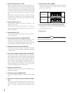
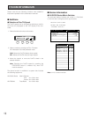
@7 Mode Selection Switch (MODE)
These switches are used to set the mode of the System
Controller connected to the Matrix Switcher. Set the
switches as shown below.
@8 Controller On/Off Switch (CONTROLLER ON/OFF)
This switch is used to turn the WV-CU550CJ system
controller power on and off.
@9 Power Cord
Normal Mode
CAM-P Mode
MODE
ON
1234
MODE
ON
1234
Refer to the Operating Instructions of the WJ-SX550C
Matrix Switcher for further details.
NOTE