


Slide #21
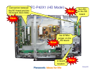
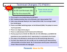
Technical Changes (TC-P42X1)
No D board
No SD Card Slot board (GS)
No Fan Drive board (PB)
These circuits are now
part of the A board
The A board is now located below the SS board.
SS11 besides providing Vsus to the SS board, now it also provides P15V
Vda is now connected directly to the C board (P35 to C25). It is no longer routed
thru the SS board.
There is no STB5V switching jumper on the SS board (SS34). The jumper is now on
the P board (P34)
There is no relays click at plug in.
There is a cable between the SC board and the SS board.
The Key input line for CH UP, CH DWN, VOL UP, VOL DWN, Menu, and INPUT/OK
operations is now routed thru the C1 board before it’s connected to the A board
The output of the SS board is monitored on the SC board (Energy Recovery)
The Scan Drive Section (SC, SU, and SD) can’t be isolated by just disconnecting
SC2 and SC20 on the Scan board. The TV shuts down and the power LED blinks 6
times if these connectors are unplugged
New