


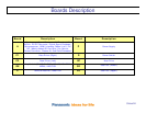

Slide #26
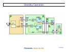
Standby Circuit Operation
When the TV is plugged in:
AC is applied to the standby circuit in the power supply to produce STB5V.
The STB5V is provided to the A board via connectors P7 (Pin 5) and P25 (Pin 9).
Connector P25 is connected to connector A25 on the A board and connectors P6 and P7 are
both connected to connector A6 on the A board.
The STB5V connected to A25 is not used during standby operation.
The STB5V from pin 5 of connector P7 is connected to pin 13 of connector A6 and is applied
to a 3.3V regulator to power the Main CPU (IC1100) on the A board. This energizes the
microprocessor (CPU) and gets it ready for program execution.
The 3.3V from the voltage regulator besides being applied to the CPU, is also applied to the
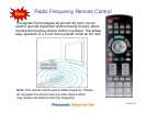
remote control receiver and the power LED on the K board through connector A1/K1 (pin 3).
If the STB5V is missing, the TV is dead (No power)