Slide #57
11 Blinks Circuit Explanation
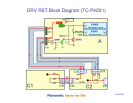
The ventilation fans are monitored to be sure they are operating properly. If one of the
fans stops or its resistance increases, the resulting current change is applied to pin 36 of
the main CPU.
The fan drive circuit is located in the A board.
The Panel-Main-On command from pin 75 of the Panel MPU (IC9003) turns on the fan
control IC (IC5740).
An increase in temperature of the TV is detected by the temperature sensor (IC4800).
This IC communicates with the main MPU (IC1100) through the IIC0 bus line.
To control the speed of the fan, a Fan-Max command from pin 44 of IC1100 is output to
the fan control IC5740.
To keep the unit cool, the fan control voltage output from IC5740 to the fans ranges
between 7V and 11V.
If this voltage exceeds 12V, D5749 conducts. The resulting voltage is then fixed at 3.3V
by D5751 and it is applied to pin 36 of IC1100 to trigger the SOS condition. The TV shuts
down and the power LED blinks 11 times.
If any of the fans becomes defective or the fan connector is removed, A high is output at
pin 6 or 9 of the fan connector (A30) to forward bias the inline diode. The DC output of
the diode is provided to pin 36 of the MPU (IC1100) to trigger the SOS condition.


