


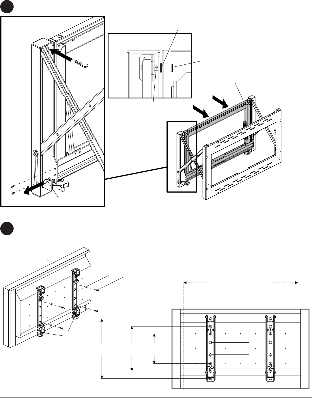
8 of 14
ISSUED: 04-23-10 SHEET #: 145-9010-2 04-27-10
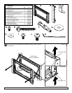
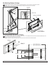
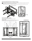
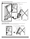
Secure display carriage by pulling release pin, fastening clevis pin, clip, four screws, and spacer as shown.
NOTE: make sure that spacer is in-between display carriage and video wall mount assembly.
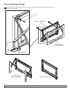
Re-Attaching Display Carriage
4
VIDEOWALL
MOUNTASSEMBLY
DISPLAY CARRIAGE
CLIP
RELEASEPIN
SCREWS
HOLEINPIN
SPACER
CLEVISPIN
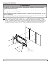
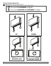
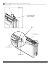
Attachadapterbrackets(B)tobackofdisplayusingfourM6x12mmphillipsscrews(I)withnylonshoulderwasher(H),orfour
M8x15mmphillipsscrews(J)asshownbelow.
NOTE: Hardware to attach dedicated plates to the mount are included with the dedicated plates.
B
H
I or J
5
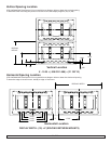
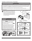
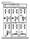
400 mm
300 mm
200 mm
PLP
MAX VESA-600 mm
MINVESA-200mm
Attaching Adapter Brackets to Display
DISPLAY