


3 of 20
ISSUED: 06-18-07 SHEET #: 095-9269-5 06-05-09
C
AA
DFB
G
A
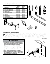
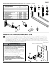
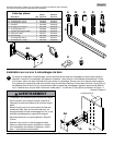
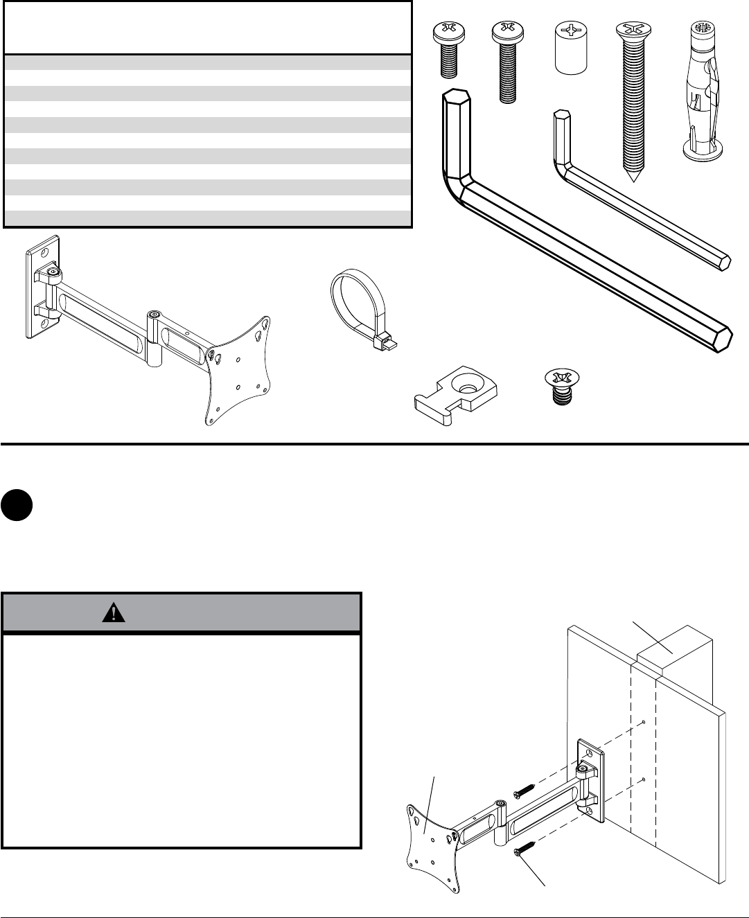
Before you begin, make sure all parts shown are included with your product.
Parts may appear slightly different than illustrated.
Parts List
PA730 PA730-S
Description Qty. Part # Part #
AA wall arm assembly 1 095-P1628 095-4268
A M4 x 12 mm phillips screw 4 504-9013 504-2014
B M4 x 20 mm phillips screw 4 504-9020 504-2013
C retaining spacer 4 590-5005 590-5003
D #14 x 2.5" wood screws 2 520-1202 520-2165
E 5 mm allen wrench 1 560-9640 560-9640
F concrete anchor 2 590-0320 590-0320
G cable ties 2 560-9711 560-2004
H cable tie anchor 2 590-1290 590-1290
I 3/16" allen wrench 1 560-0071 560-0071
J 8-32 x 1/4" flat head screw 2 520-1622 520-2622
E
I
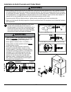
• Installer must verify that the supporting surface will
safely support the combined load of the equipment
and all attached hardware and components.
• Tighten wood screws so that wall plate is firmly at-
tached, but do not overtighten. Overtightening can
damage the screws, greatly reducing their holding
power.
• Never tighten in excess of 80 in. • lb (9 N.M.).
• Make sure that mounting screws are anchored into
the center of the stud. The use of an "edge to edge"
stud finder is highly recommended.
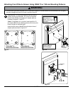
WARNING
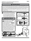
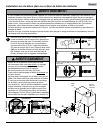
Using a stud finder, locate and mark the edges of the wood stud used in mounting this product. Use of an edge to
edge stud finder is highly recommended. Use a level to draw a vertical line down the center of the stud. Use wall
plate as template to mark center of holes along the vertical line. Drill two 5/32" (4 mm) dia. holes 2.5" (64 mm)
deep. Attach wall arm assembly (AA) to wall using two #14 x 2.5” flat head wood screws (D) as shown in figure
1.1.
Skip to step 2.
1
Installation to Wood Stud Wall
D
WOOD STUD WALL
AA
fig. 1.1
H
J