


5 of 20
ISSUED: 06-18-07 SHEET #: 095-9269-5 06-05-09
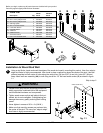
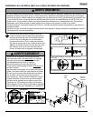
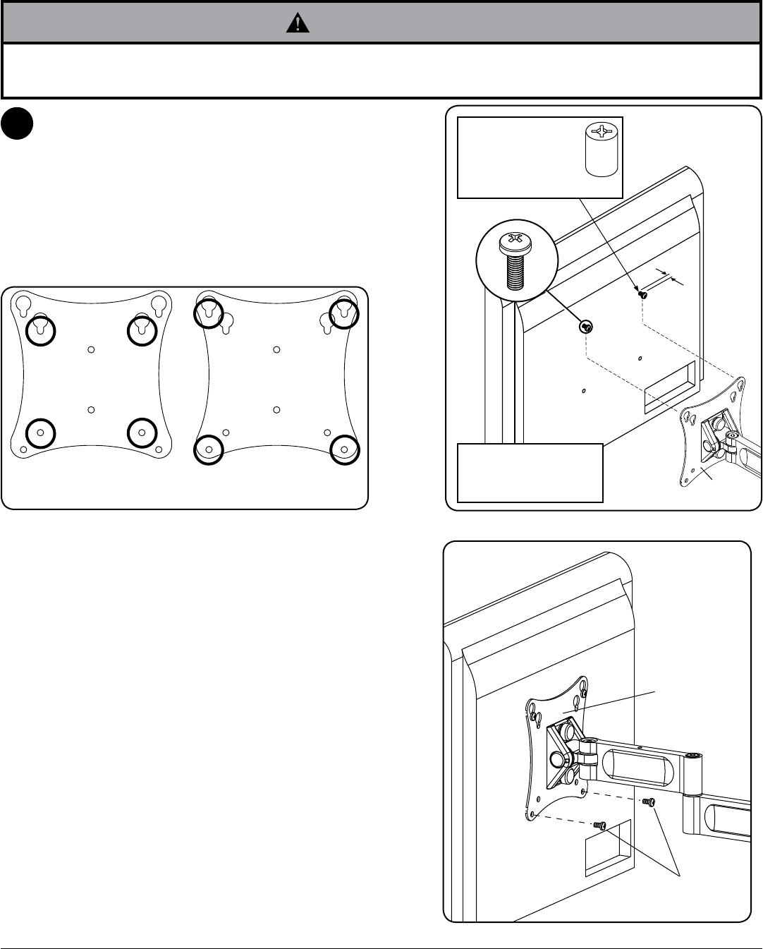
fig. 2.3
A or B
ADAPTER
PLATE
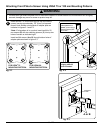
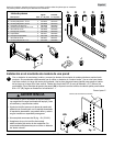
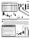
Insert two M4 x 12 mm screws (A) into top two holes of
screen, leaving approximately .25" (6 mm) of exposed
thread. Hook screws onto keyslots of adapter plate as
indicated in figures 2.1 and 2.2.
*Note: If hole pattern is in a pocket, insert two M4 x 20
mm screws (B) with two retaining spacers (C) into top two
holes of screen as indicated right.
Insert two M4 screws (A or B) through bottom holes of
adapter plate as shown in figure 2.3.
2
fig. 2.1
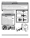
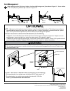
• If screws don’t get three complete turns in the screen inserts or if screws bottom out and bracket is still not tightly
secured, damage may occur to screen or product may fail.
WARNING
1/4”
fig. 2.2
A
Screen may appear
slightly different
than illustrated
C
*For screens with
a hole pattern in a
pocket, spacers (C) go
between adapter plate
and screen.
FOR VESA
®
75
MOUNTING PATTERN:
FOR VESA
100
MOUNTING PATTERN:
Attaching Front Plate to Screen Using VESA 75 or 100 mm Mounting Patterns
ADAPTER
PLATE