


6 of 20
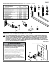
ISSUED: 06-18-07 SHEET #: 095-9269-5 06-05-09
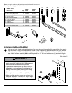
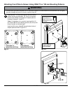
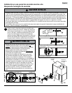
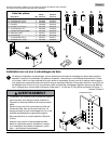
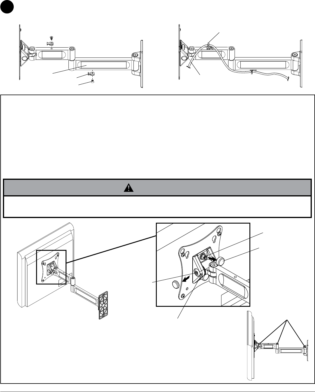
Attach cable tie anchor (H) to top or bottom of wall arm (AA) using screw (J) as shown in figure 3.1. Secure cables
to wall arm (AA) using cable tie (G) as shown in figure 3.2.
Cord Management
fig. 3.1
SCREEN
CABLES
J
H
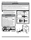
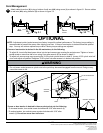
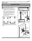
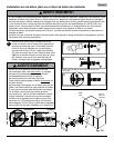
NOTE: Adjustment points (socket screws) are factory torqued for optimal performance. This factory torque setting is
recommended to prevent the screen from slipping over time. If more or less tension is desired follow this optional
step. You may not achieve optimal torque value if factory torque settings are adjusted.
If more or less tension is desired in the tilt mechanism, do the following:
• To adjust tilt, insert a flat head screw driver into slot and remove cap covering the socket screw. Tighten or loosen
socket screw no more than half a turn using 5 mm allen wrench (E) as shown in detail 2.
• To adjust roll, remove snap caps covering the 10-32 nylock nuts as shown in detail 2. Loosen 10-32 nylock nuts half
a turn and adjust roll position. Retighten 10-32 nylock nuts after screen is in desired roll position.
OPTIONAL
SNAP CAP
SOCKET
SCREW
10-32 NYLOCK NUT
DETAIL 2
SLOT
• Do not loosen socket screws or nylock nuts to the point they become disengaged from the mount. Doing so may
cause the screen to fall.
WARNING
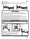
If more or less tension is desired in the arm pivot points, do the following:
• To increase tension, turn socket screw clockwise with 3/16" allen wrench (I).
• To reduce tension, turn socket screw counter-clockwise with 3/16" allen
wrench (I). Do not turn more than half a turn.
SOCKET SCREWS
3
© 2009, Peerless Industries, Inc. All rights reserved.
All other brand and product names are trademarks or registered trademarks of their respective owners.
Peerless Industries, Inc.
3215 W. North Ave.
Melrose Park, IL 60160
www.peerlessmounts.com
AA
G
fig. 3.2