


5 of 9 ISSUED: 05-02-06 SHEET #: 202-9112-3 12-05-06
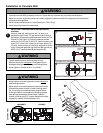
IMPORTANT! Concrete must be 2000 psi density
minimum.
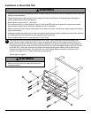
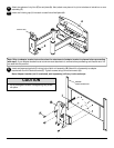
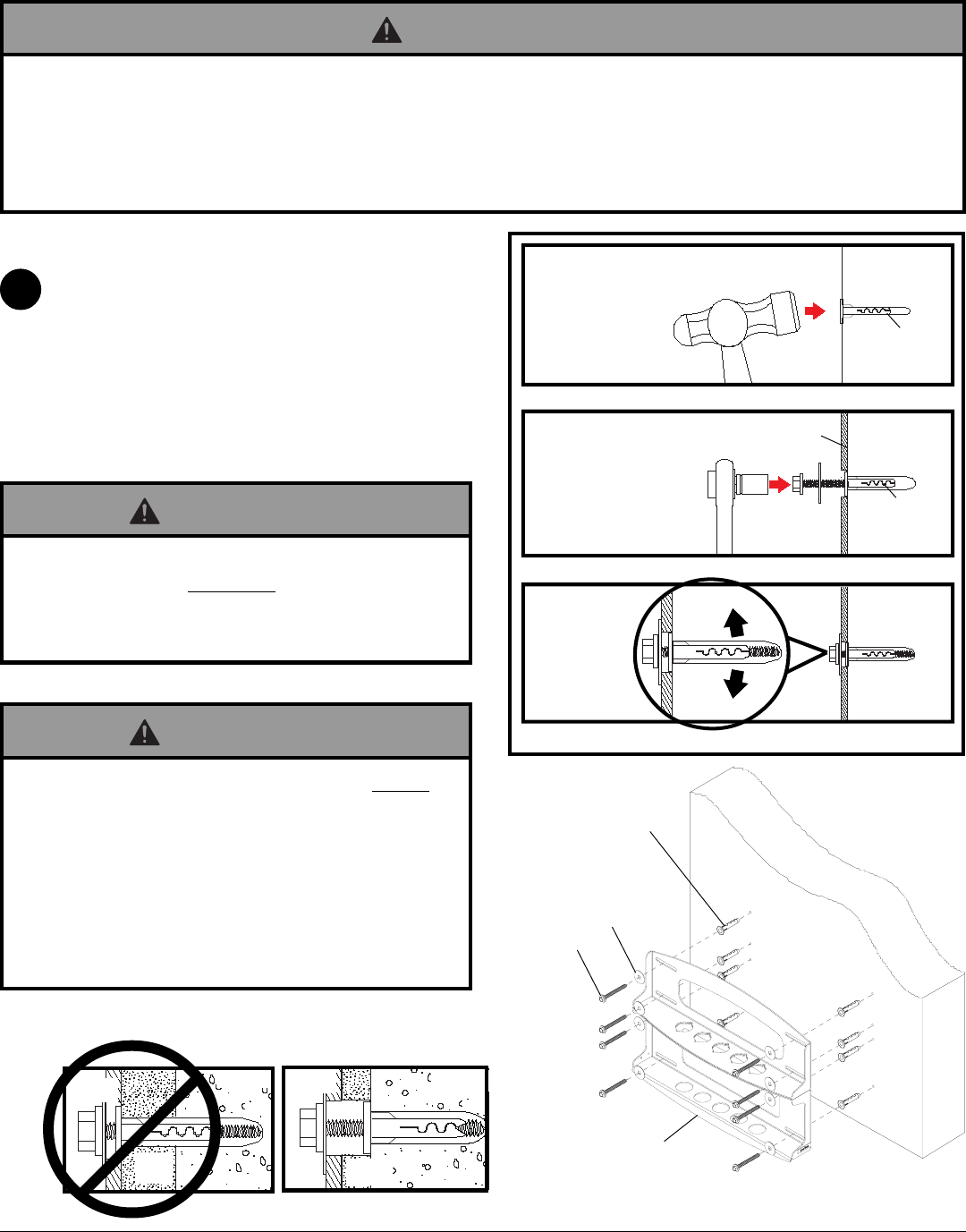
Use wall plate (A), making sure that it is level, as a
template to mark holes. The top mounting slots should
be located .36" above the desired screen center for PLA
60 and PLA 60-S and .43" below the desired screen
center for PLAV 60 and PLAV 60-S. Use the masonry bit
to drill 5/16" (8 mm) dia. holes to a minimum depth of 3"
(76 mm). Insert anchors in holes flush with wall as shown
(right). Place wall plate (A) over anchors (W) and secure
with 5/16 x 3" wood screws (O) and washers (P).
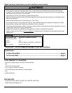
• Concrete must be 2000 psi density minimum. Lighter density concrete may not hold concrete anchor.
• Make sure that the supporting surface will safely support the combined load of the equipment and all attached
hardware and components.
• Never exceed the Maximum UL Load Capacity of 175 lb (79 kg).
• Never mount this product to metal studs.
WARNING
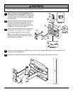
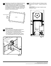
• Always attach concrete expansion anchors directly to
load-bearing concrete.
• Never attach concrete expansion anchors to concrete
covered with plaster, drywall, or other finishing mate-
rial. If mounting to concrete surfaces covered with a
finishing surface is unavoidable, the finishing surface
must be counterbored as shown below. If plaster/
drywall is thicker than 5/8", custom fasteners must be
supplied by installer (Not evaluated by UL).
WARNING
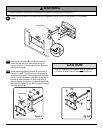
• Tighten wood screws so that wall plate is firmly
attached, but do not overtighten. Overtightening can
damage screws, greatly reducing their holding power.
• Never tighten in excess of 80 in • lb (9 N.M.).
WARNING
1
Installation to Concrete Wall
A
O
P
W
concrete
surface
1
3
2
Drill hole(s) and insert anchor(s) (W)
mounting
plate
Place plate over anchor(s) (W) and secure with screw(s)(O)
Tighten all fasteners
W
W
CUTAWAY VIEW
INCORRECT
CORRECT
mounting
plate
plaster/
dry wall
concrete
mounting
plate
concrete
plaster/
dry wall