


8 of 9
ISSUED: 05-02-06 SHEET #: 202-9112-2 06-21-06
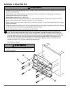
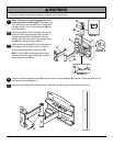
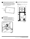
Insert two M10 screws (F) into swivel box on arm assembly (C) as shown. Leave approx. 1/4" of exposed
thread.
.25"
F
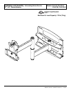
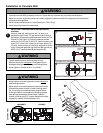
• Use an assistant or mechanical lifting equipment to safely lift and position the plasma TV.
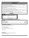
WARNING
• After tilt is adjusted, all fasteners must be tightened.
Failure to do so will result in damage to the mount.
CAUTION
6
6-1
6-2
fig 6.1 fig 6.2
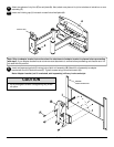
SWIVEL BOX
Hook tilt-roll assembly (B) onto M10 screws (F).
Insert carriage bolt (I) into slot of swivel box as
shown in figure 6.1. Install nylon washer (G) and tilt
adjustment knob (H).
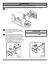
Install remaining two M10 screws (F) as shown in
figure 6.2. HAND TIGHTEN all four M10 screws to
allow for tilt adjustment. Remove tape from carriage
bolt (I). For tilt adjustment, push back on the top of
plasma to relieve pressure on knob. Adjust tilt to
desired position and tighten tilt adjustment knob (H),
then securely tighten all four M10 screws (F) using 6
mm allen wrench (U).
I
B
F
H
G
SWIVEL BOX
H
F
I
C