Pelco Manual C1943M (9/99) 17
OPERATIONAL OVERVIEW
The basic function of the VCRC-P unit is to act as an interface between the user/operator
of the system and any connected VCRs. Each VCRC-P processes and executes only com-
mands with addresses that match the controller address. When a VCRC-P receives a com-
mand with an inappropriate address it passes it on to the next unit (if applicable) via its
OUT port.
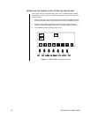
When power is first applied to the unit, RAM is cleared and initialization routines are called.
The power LED is lit, operational chips are configured, interrupt priorities are set and the
activity LED on the front panel of the unit flashes on and off at about 1/2 second intervals.
The unit is waiting for its first valid command.
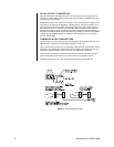
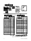
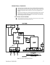
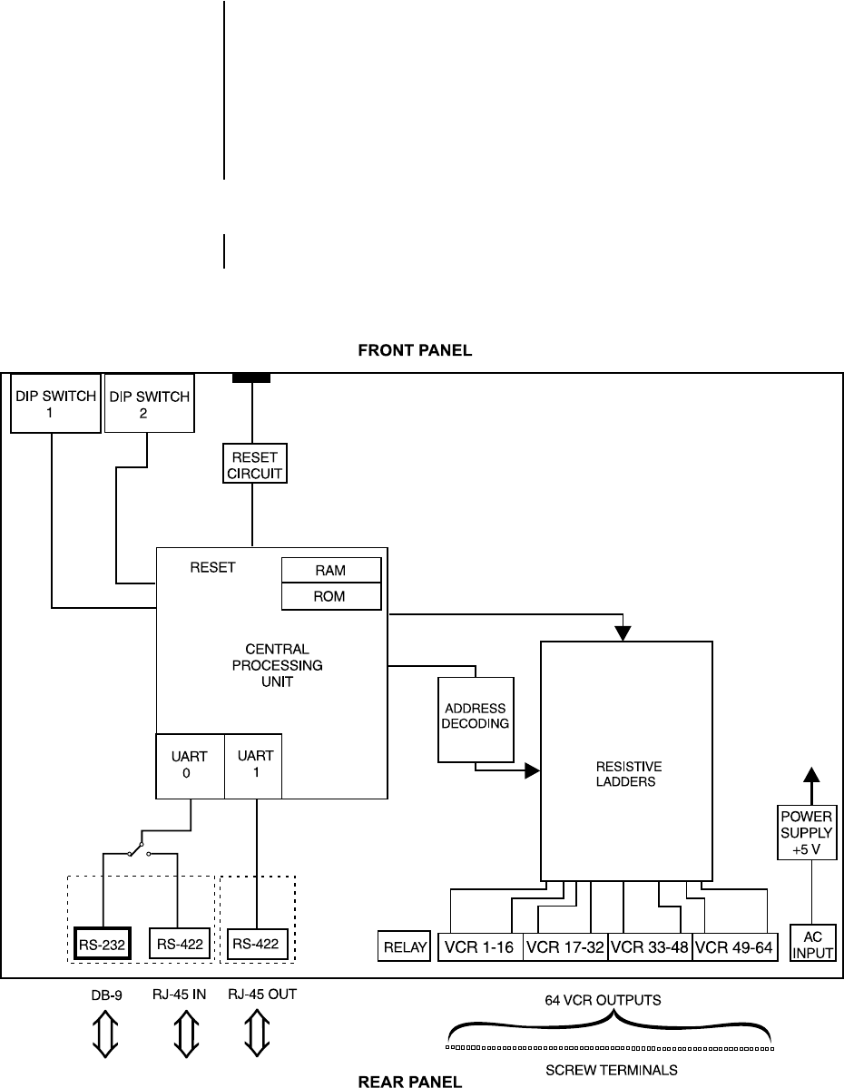
FUNCTIONAL BLOCK DIAGRAM
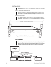
The block diagram below represents a combination of internal circuitry as well as software
controlled hardware within the CM9760-VCRC-P unit.
Figure 16. VCRC-P Functional Block Diagram


