Pelco Manual C544M (2/98) 9
3.2.1 Setting the Start Address
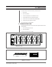
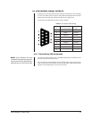
Each Pelco CM9760-IRC unit requires a six-bit start address. The start address is
configured using the DIP switches on the communication card (see Figure 5: DIP
switches). Each control card occupies one address space. An IRC unit occupies
four address spaces (if there are only two control cards in the unit, it still occupies
four address spaces).
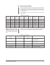
The start address of an IRC unit is set with the DIP switches on the communication
card per Table B.
Table B. Start Addresses
DIP DIP DIP DIP DIP DIP Start Address Start Address
Switch 8 Switch 7 Switch 6 Switch 5 Switch 4 Switch 3 (Binary) (Decimal)
ON ON ON ON ON ON 000000 0
ON ON ON ON ON OFF 000001 1
ON OFF ON ON ON ON 010000 16
ON OFF ON ON OFF ON 010010 18
OFF OFF ON ON OFF ON 110010 50
OFF OFF OFF OFF OFF ON 111110 62
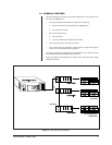
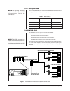
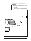
Unlike an IRC unit, a serial GPI occupies one address space. In the sample system
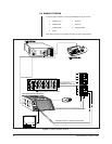
outlined in Figure 3, the start addresses would set up according to Table C.
Table C. Start Addresses
Device Address (Decimal) Address (Binary)
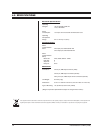
Serial GPI 0 000000 Set via serial GPI communication
card DIP switches
IRC unit 1/control card 1 1 000001 Set via IRC unit 1 communication
card DIP switches
Control card 2 2 000010 Automatic internal default
Control card 3 3 000011 Automatic internal default
Control card 4 4 000100 Automatic internal default
NOTE:
It is necessary only to set the
start address of the IRC as a whole.
The start address of each control
card in the unit is set by internal de-
fault.


