C2968M-A (10/09) 9
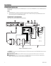
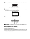
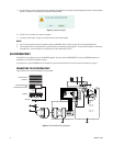
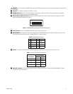
ᕣ Keyboard Data and DIP Switch Cover: Contains the keyboard configuration switches. Use the switches to configure the keyboard
address and operational mode (refer to Figure 2).
Figure 2. KBD300A Switch Settings: DX4500/DX4600 Operation
ᕤ RJ-45 Connector: Connects the KBD300A to the terminal block using the RJ-45 cable.
ᕥ KBDKIT/KBDKIT-X: The keyboard wiring kit that provides power for the KBD300A keyboard and interfaces the keyboard to the PV140.
The kit includes two RJ-45 wall blocks and a 120 VAC/230 VAC to 12 VAC transformer.
ᕦ PV140: A user-supplied interconnect cable (shielded twisted pairs) is required to connect the PV140 to the terminal block.
ᕧ USB to RS-232 Cable: A USB to RS-232 converter cable (with a DB9 male connector) is included with the KBD300USBKIT. The cable
connects the PV140 to the DX4500/DX4600.
ABOUT SOFTWARE UPDATES FOR THE DX4500/DX4600
Before you begin updating your DX4500/DX4600, be sure to observe the following information:
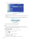
• Your current DVR configuration settings are not deleted or replaced during the update process.
• Download the required update files from www.pelco.com.
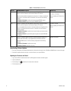
• Your unit might require more than one update. Refer to the DX4500/DX4600 product label for the unit’s version (1.2, V1.3, or A1.3). Then
refer to Table C on page 10 for the required update files and procedures.
• You must use a USB drive to update the DX4500/DX4600 firmware and software. The update file must be the only file on the USB drive, and
it must be located in the USB drive root directory.
Table A. RJ-45 Wall Block Pinouts
Pin Signal Pin Signal
1TX+ 5GND
2TX- 6N/A
3 12 VAC/DC 7 RX-
4 Nonpolar 8 RX+
Table B. PV140 to RJ-45 Wall Block Connections
RJ-45 Wall Block
PV140 Signal To Pin Signal
RX+ 1 TX+
RX- 2 TX-
TX- 7 RX-
TX+ 8 RX+
DOWN = ON
12345678
ON


